Announcement

Collapse
No announcement yet.

Square wave testing guitar amp OT

Collapse
X
 
  • Filter
  • Time
  • Show
Clear All
new posts

  • Square wave testing guitar amp OT

    As we know guitar OTs are not designed to pass the full audio band and have their LF and HF limits. Sometimes a guitar amp is designed around a HiFi specs OT but most of time it's not the case.
    Considering the above and that a square wave contains F/1 to F*10 of the fundamental how adequate is to run the "standard" 100Hz/1kHz/10kHz test on a guitar amp/OT? Some suggest that running a square wave below 300Hz and above 2kHz in a guitar amp is useless.
    Also at what power should the test be performed in order to adequately diagnose any existing problems - 1V, half power, full power?

  • #2
    I would think that full-power square waves at 100Hz and 1kHz would be reasonable. A square wave at 10kHz is daft (even for hi-fi) in my opinion, but then I may be influenced by my own hearing which doesn't really go beyond about 8kHz . (It's an age thing.)
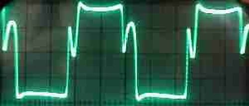
    The square wave would have to be injected just before the PI, to avoid too much tone-shaping from the pre-amp, but even then a presence control would alter the square wave shape.

    I'm not sure what kind of 'problems' the test would identify (beyond the fact that the OT is either working or not). However, I think these tests could give an interesting comparison between different guitar amp power stages.
    Last edited by Malcolm Irving; 04-23-2018, 08:07 PM.

    Comment


    • #3
      The point of a square wave is that the leading and trailing edges represent the higher freqs. If your circuit lacks high end response, your square wave corners will be rounded off.

      I am not sure a guitar amp is designed around a hifi transformer. I would tend to think it is more like a guitar amp was designed, and they grabbed a hifi transformer to use in it.
      Education is what you're left with after you have forgotten what you have learned.

      Comment


      • #4
        I am not sure a guitar amp is designed around a hifi transformer. I would tend to think it is more like a guitar amp was designed, and they grabbed a hifi transformer to use in it.
        Actually it's more like that.

        I'm asking because recently I was retubing an amp that I'm using and decided to run some square waves. 100Hz and 1kHz were nothing unusual but the 10kHz one was very strange - asymmetric, with a dip at the bottom. The OT is a 4k2 primary, leakage inductance was measured at 22mH. According to theory the OT should be able to up to 30kHz but the 10kHz sine wave didn't look very good either so I was wondering if I was doing something wrong.
        I also ran square waves at 2, 3 and 5kHz and they looked kind of OK but the 10kHz was a different story.

        Comment


        • #5
          Through the amp? If so, why blame the transformer?
          Education is what you're left with after you have forgotten what you have learned.

          Comment


          • #6
            It's a simple clean setup - a 12AX7 in parallel, with 3 options for the cathode (3 ways switch) - non bypassed and 1uF/10uF bypassed going to Volume and to the PI. I was testing with the cathode unbypassed in order to avoid tone shaping.
            There's an added Depth and Presence control the Peavey 5150 style but they were all at zero. The NFB resistor is variable from 220k to 47k and the 10kHz square wave is most problematic when at 47k.
            Last edited by GainFreak; 04-23-2018, 09:44 PM.

            Comment


            • #7
              Originally posted by GainFreak View Post
              It's a simple clean setup - a 12AX7 in parallel, with 3 options for the cathode (3 ways switch) - non bypassed and 1uF/10uF bypassed going to Volume and to the PI. I was testing with the cathode unbypassed in order to avoid tone shaping.
              There's an added Depth and Presence control the Peavey 5150 style but they were all at zero. The NFB resistor is variable from 220k to 47k and the 10kHz square wave is most problematic when at 47k.
              Too much garbage and tone shaping in the middle, test is useless.

              Measure OT squarewave response *only* when driving it straight from a generator (if it can drive it) or through an SS amp which itself is flat from, say, 10Hz to 100kHz , thus having a 10:1 frequency "safety factor" at each end and is very low impedance (high damping factor) so it behaves as a perfect voltage source.

              And "guitar clean" is **horrible** "Hi Fi amp" performance under any parameter choice.
              Juan Manuel Fahey

              Comment


              • #8
                I would have thought that any value of testing using a square wave would come from it indicating unstable conditions arising from the use of feedback (eg. via typical return of speaker signal back to presence pot region). Feedback loop instability can show as ringing on the top of the square wave, but that assumes the square waveform test signal can make it to the stages that include feedback (and not get tone shaped beforehand). So the circuit of the amp needs to be appreciated for starters, as a feedback loop has to be identified and then a signal injection point has to be identified that is beforehand.

                For diy amps, I would recommend scoping the speaker output (with a resistive load only) using a spectrum analyser (ie. soundcard and software) and looking for stray higher frequency signals coming out of the noise floor as all pots are increased and with some lower frequency sine input - it is not uncommon for stray feedback to occur due to wiring layout or proximity of output transformer to low level signal stages, and that can show up as a new 'signal' that would end up being heard as a feedback squeal.

                And if you have a soundcard/software setup then it is amazingly easy to do signal frequency sweeps at different pot settings to appreciate what tone shaping is actually being done by the amp, as a way to augment what your ears are hearing (although the speaker is not typically included in this type of test). If you have a good soundcard that can extend out to 30-40kHz (ie. 96kHz sampling at least) then that can also identify peaks in output response at higher frequencies that can indicate feedback induced instability

                Comment


                • #9
                  There is another thing to be aware of in square wave testing - phase response. For real -world filters made of Rs, Cs and Ls, there will always be a phase shift, starting at 1/10 the filter turnover frequency and continuing up to 10x the filter turnover for single pole filters. Add a pole, add more phase shift. Yes there are RLC filter designs that deliberately try to use compensating phase shifts to nullify some of this. Hifi crossover work led in a lot of this, because hifi crazies still believe you can hear phase shift even in the absence of something to reinforce or cancel.

                  But in a guitar amp with typical tone controls, you have no particular way to get phase invariance. Phase linearity is all you could hope for, but usually don't get.

                  That means that the harmonics in a waveform anywhere near a filter frequency get phase shifted from the fundamental. The result may have the right harmonics, even the right amplitudes on them, but combining them to equal a square wave on a scope is not necessarily conserved.

                  This struck me long ago when I was having trouble doing my favorite clipping test, using a triangle wave. Triangles are several times easier than sines to see the first hints of clipping on, as those lovely triangle peaks get flattened first. Hard to see on a sine. But anything with tone controls makes this almost impossible as the harmonics' phases that make it reassemble into a triangle get phase shifted and it won't look triangular any more.

                  Sigh. Nature is a set of equations, and we even had to go figure them out ourselves.
                  Amazing!! Who would ever have guessed that someone who villified the evil rich people would begin happily accepting their millions in speaking fees!

                  Oh, wait! That sounds familiar, somehow.

                  Comment


                  • #10
                    Thanks for your replies.
                    What is strange I got some ringing and overshoot on the bottom part of the square wave only. The signal was fed directly to the PI. I'll have to investigate further and take some screenshots.

                    Comment


                    • #11
                      The two sides of the PI don't get their signal from the same place, so I am not surprised there are differences.
                      Education is what you're left with after you have forgotten what you have learned.

                      Comment


                      • #12
                        Agree and add: if you want to split hairs with the analysis, you may think the push pull amplifier as really *two* amplifiers .
                        Two separate single ended ones, **each one** with its own gain, phase shifts, stability, whatever, just thatbthey work together for a specific goal.
                        One is the "top half" one, made out of one PI triode and its matching output tube(s) and basically dedicated to the top half of the sinewave, and the "bottom half" which does the symmetrical thing.
                        Yes, of course both halves are combined by the OT and fed to the speaker ... but notice that is done *after* they have done their thing , each on its own.

                        Whatīs my point?: that being two separate amplifiers, one may very well be stable, while the other may not.
                        And signal output from each half may be quite different.
                        Even if "circuit" is the same, tubes involved are not.
                        We are already aware that power tubes vary wildly , thatīs why we often ask for "matching" , in some cases use separate biasing pots, etc. , but 99,9% of the time we forget or ignore that both halves in the same tube (12A*7 for example) can be quite different.

                        Why do I mention this? .... itīs the only explanation I find for 2 things :

                        * the signal waveform assymetry I always see in non NFB amplifiers , unless I take special care in matching tubes .
                        This is an overdriven Marshall 20 watt, no NFB, notice signal is very assymetrical:


                        * amp may be stable on one half the wave, and unstable on the other half:
                        Juan Manuel Fahey

                        Comment


                        • #13
                          But during the A part of the AB cycle a different set of properties are in effect, and so it is even more "interesting".

                          Comment


                          • #14
                            Couple of screenshots taken with no FB and with FB. PI is LTPI 82k/100k "standard' type found in most amps. FB resistor is 47k, signal fed directly to PI, close to full power. Obviously the FB loop is causing instability.

                            Click image for larger version

Name:	5kHzFullNoFB.jpg
Views:	1
Size:	47.2 KB
ID:	849406

                            Click image for larger version

Name:	5kHzFullFB.jpg
Views:	1
Size:	49.3 KB
ID:	849405

                            Click image for larger version

Name:	10kHzFullNoFB.jpg
Views:	1
Size:	47.6 KB
ID:	849408

                            Click image for larger version

Name:	10kHzFullFB.jpg
Views:	1
Size:	47.5 KB
ID:	849407

                            Comment


                            • #15
                              Can you measure the level of feedback - eg. constant input level, and difference in output voltage in dB when comparing no FB to full FB.

                              That ringing on 5kHz doesn't suggest instability, just a bit low of margin.

                              Comment

                              Working...
                              X