Announcement

Collapse
No announcement yet.

Power Transformer wiring help!!!

Collapse
X
 
  • Filter
  • Time
  • Show
Clear All
new posts

  • Power Transformer wiring help!!!

    Hello, I'm building kind of a one-off amp. It will be a single ended 6l6 amp using a Fender Champ 12 PT and OT [fenders mid 80's red knob 6l6 champ] and a fender musicmaster bass amp layout, with one 12ax7 and a small interstage transformer as a phase inverter. You may be asking why build a single ended musicmaster bass amp? Well,I have all the parts from two DOA amps and it should be a relatively simple build and kind of unique! However, I'm stumped with the champ 12 Power Transformer. Its a Schumaker I believe and has the usual two red,2 green and a yellow 240 volt tap [I'm in the EU]. It has a grey wire that went to the on/off switch on the champ 12 and a black wire that went from the fuse to the on/off switch next to the grey wire. It also has a blue and brown that are wire nutted together and an orange that is cut and was wire nutted.
    My problem is that there is a red and yellow PT wire on the musicmaster bass amp layout that goes to the 220ohm cathode resistor. The Champ 12 PT does not have this wire color code so I'm at a stand still. [See attached Musicmaster Bass layout]

    http://file:///C:/Users/Uzivatel/Des...hem_layout.pdf

    Click image for larger version

Name:	IMG_3233.jpg
Views:	1
Size:	47.1 KB
ID:	873729


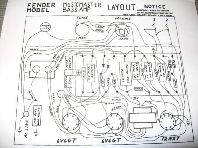
    My question is this, how can I find out if one of my champ 12 PT wires can be used for this cathode resistor location, specifically one of the un-used wire nutted blue,brown or orange wires.
    I know this might be a lame question, but this is my first build and its the only thing stumping me!
    [If this helps, the black PT wire shows continuity with the blue and brown wire nutted wires]
    Last edited by czech-one-2; 06-26-2018, 02:09 PM.
    https://soundcloud.com/damalistik/ro...ival-dubplatessigpic

  • #2
    Heres some photos of the champ 12 PT. On one side,the two red wires have been extended with orange, the two heater wires are green/yellow.
    On the other side is the blue/brown nutted wire,the cut orange, the grey that went to the on/off switch and the yellow which was the 240v tap.

    Click image for larger version

Name:	IMG_0099.JPG
Views:	2
Size:	628.4 KB
ID:	849990

    Click image for larger version

Name:	IMG_0102.JPG
Views:	1
Size:	585.3 KB
ID:	849991

    Click image for larger version

Name:	IMG_0103.JPG
Views:	1
Size:	587.8 KB
ID:	849992

    Click image for larger version

Name:	IMG_0104.JPG
Views:	1
Size:	618.3 KB
ID:	849993

    Click image for larger version

Name:	IMG_0101.JPG
Views:	1
Size:	650.7 KB
ID:	849994
    Last edited by czech-one-2; 06-26-2018, 02:12 PM.
    https://soundcloud.com/damalistik/ro...ival-dubplatessigpic

    Comment


    • #3
      this is your PT schematic
      http://el34world.com/charts/Schemati...p_12_schem.pdf

      you can see the difference,no center tap in your PT,that goes to ground.
      Primary leave it like that,feed voltage to grey and black,how much voltage do you get on the red/red secondary?

      Comment


      • #4
        Originally posted by alexradium View Post
        this is your PT schematic
        http://el34world.com/charts/Schemati...p_12_schem.pdf

        you can see the difference,no center tap in your PT,that goes to ground.
        Primary leave it like that,feed voltage to grey and black,how much voltage do you get on the red/red secondary?
        Well, the amp is in its beginning stages and not wired up,I'm just laying it out so there is no voltage as of yet. So with no center tap that goes to the cathode resistor, is this project doomed??? Does that mean I have to buy a PT?
        https://soundcloud.com/damalistik/ro...ival-dubplatessigpic

        Comment


        • #5
          You are focusing on "the red wire goes to the cathode resistor." What you should focus on is the overall CIRCUIT. Draw a schematic of exactly what you plan to build. THEN where which wire goes will be more clear.

          The wire from the transformer was a center tap that went to ground, It is soldered to the resistor simply because that end of that resistor was the nearest grounded point on the layout. Follow on your layout that red/yellow wire is soldered to the resistor, yes, but continues along teh side of the board until it gets grounded over near the input jacks.

          Your transformer lacks a center tap, so you cannot make the full wave power supply of the Musicmaster. You could wire a bridge rectifier across the red wires for a lowish B+ voltage, or duplicate the Champ12 doubler for about 500v.
          Education is what you're left with after you have forgotten what you have learned.

          Comment


          • #6
            Originally posted by Enzo View Post
            You are focusing on "the red wire goes to the cathode resistor." What you should focus on is the overall CIRCUIT. Draw a schematic of exactly what you plan to build. THEN where which wire goes will be more clear.

            The wire from the transformer was a center tap that went to ground, It is soldered to the resistor simply because that end of that resistor was the nearest grounded point on the layout. Follow on your layout that red/yellow wire is soldered to the resistor, yes, but continues along teh side of the board until it gets grounded over near the input jacks.

            Your transformer lacks a center tap, so you cannot make the full wave power supply of the Musicmaster. You could wire a bridge rectifier across the red wires for a lowish B+ voltage, or duplicate the Champ12 doubler for about 500v.
            Yes, I'm kinda painting by numbers. Enzo, I have the power supply board from the champ 12, it is not damaged. But I dont know how to integrate that into my Musicmaster bass circuit board?
            https://soundcloud.com/damalistik/ro...ival-dubplatessigpic

            Comment


            • #7
              Could you recommend a PT with a center tap that would work in this amp?
              https://soundcloud.com/damalistik/ro...ival-dubplatessigpic

              Comment


              • #8
                In any case you can not repeat not build this:

                Originally posted by czech-one-2 View Post
                Hello, I'm building kind of a one-off amp. It will be a single ended 6l6 amp using a Fender Champ 12 PT and OT [fenders mid 80's red knob 6l6 champ] and a fender musicmaster bass amp layout, with one 12ax7 and a small interstage transformer as a phase inverter.
                Simply because single ended amplifiers do NOT have Phase Inverters, even less transformer driven ones.

                You may be asking why build a single ended musicmaster bass amp? Well,I have all the parts from two DOA amps and it should be a relatively simple build and kind of unique!
                If you have half a submarine and half a plane there is no way you can not use those to build a submaplane.
                Unique? ... sure !!!
                Will it work? .... mmmmhhhh .... no.

                However, I'm stumped with the champ 12 Power Transformer. Its a Schumaker I believe and has the usual two red,2 green and a yellow 240 volt tap [I'm in the EU]. It has a grey wire that went to the on/off switch on the champ 12 and a black wire that went from the fuse to the on/off switch next to the grey wire. It also has a blue and brown that are wire nutted together and an orange that is cut and was wire nutted.
                Rebuild the original Champ power supply, in full.
                Then you´ll have a certain +V (whatever the Champ used) and 6.3V filament voltage, suitable for one 6L6 and two 12AX7.
                You can build any Bass amplifier which is happy with tat tube complement.
                In fact, the Champ 12 as-is is a good Bass amp ... not too different from a Blackface Bassman, where the "good" channel was the "normal" one, the so called "Bass" one being muddy.
                You just need a Bass speaker in a closed or tuned box of suitable volume instead of a shoebox sized open back one, which is fine for guitar

                My problem is that there is a red and yellow PT wire on the musicmaster bass amp layout that goes to the 220ohm cathode resistor. The Champ 12 PT does not have this wire color code so I'm at a stand still. [See attached Musicmaster Bass layout]
                Forget the Musicmaster layout and even more "playing by the colours" because they don´t necessarily match AT ALL and mistakes here go from dangerous to deadly.
                Just rebuild the Champ 12 Power Amp and supply, and add whatever preamp you fancy ... even an Ampeg type one.
                12 PT wires can be used for this cathode resistor location, specifically one of the un-used wire nutted blue,brown or orange wires.
                I know this might be a lame question, but this is my first build and its the only thing stumping me!
                [If this helps, the black PT wire shows continuity with the blue and brown wire nutted wires]
                See above suggestion.

                And please post schematics, raw layouts are incomplete and create more questions than they answer.
                Juan Manuel Fahey

                Comment


                • #9
                  ^ thanks for that reply. It looks like my idea was destined to fail....
                  I guess I will just build a Musicmaster Bass amp at this point, I'll just have to order a suitable PT.
                  https://soundcloud.com/damalistik/ro...ival-dubplatessigpic

                  Comment


                  • #10
                    I guess I read the premise differently. I read the mention of phase inverter as part of the description of the musicmaster amp.

                    So right or wrong I assumed he planned to use the preamp of the Musicmaster with a basic Champ single ended PA. To whatever extent they may be different.

                    The Musicmaster does have the transformer phase inverter. DO you have that transformer?
                    Education is what you're left with after you have forgotten what you have learned.

                    Comment


                    • #11
                      Yes Enzo, I do. Its a fender reverb transformer from a vibro king amp . It can only feed one power valve though as it has the green wire that goes to pin 5 of the valve, but not the yellow that goes to pin 5 of the other power valve. Which is why I thought I could use it to build a single ended amp with the interstage transformer phase inverter.
                      Last edited by czech-one-2; 06-26-2018, 10:34 PM.
                      https://soundcloud.com/damalistik/ro...ival-dubplatessigpic

                      Comment


                      • #12
                        Originally posted by Enzo View Post
                        I guess I read the premise differently. I read the mention of phase inverter as part of the description of the musicmaster amp.

                        So right or wrong I assumed he planned to use the preamp of the Musicmaster with a basic Champ single ended PA. To whatever extent they may be different.
                        That was my plan, but I've got one toe in the kiddie pool and am already in over my head...
                        https://soundcloud.com/damalistik/ro...ival-dubplatessigpic

                        Comment


                        • #13
                          OK, It would be possible to drive a single output tube from one side of a transformer in similar fashion, but a reverb transformer is very different from an interstage transformer. The black and green wires are expecting to drive an 8 ohm reverb transducer - about the same as driving a small speaker. Your power tube grid wants to see thousands of ohms, not just 8.
                          Education is what you're left with after you have forgotten what you have learned.

                          Comment


                          • #14
                            Ok Enzo, looks like I'm way off track. I'm really trying to just salvage these parts instead of trashing them. Can I ask you one last question [for now] ;-)
                            What would you build with the Champ 12 PT/OT and chassis? I'll forget my Musicmaster Bass idea....
                            https://soundcloud.com/damalistik/ro...ival-dubplatessigpic

                            Comment


                            • #15
                              I am not the build something out of something else guy around here. The Champ is a single ended amp. You can make a single tube power amp , based on a Champ with it. I see no reason you couldn't take the front end of the Musicmaster Bass, and couple it to that power amp. Look at the Champ 12 circuit from afar. I mean hold the drawing three feet away so the details don't bog you down. It is a basic preamp using three triodes (one and a half 12AX7) They added in a bunch of "channel switching stuff you could leave out. or for that matter include.

                              Champ 12 used the leftover half tube for a reverb. And look, they used an OOOLLLDDDD trick for the reverb, they drive the reverb pan directly from the speaker output. Saves a whole drive circuit. They added a JFET Q1, as the recivery input. And they stole a supply voltage for that JFET from the power tube cathode voltage. SO they didn't even have to make a low voltage supply. You could leave the whole reverb out of you like.
                              Education is what you're left with after you have forgotten what you have learned.

                              Comment

                              Working...
                              X