 Tweet
Tweet
Originally posted by pdf64
View Post
-
Yeah I looped it around the other side and it got significantly better. Thanks! -
I'm a bit surprised at the comments about the recording preamp. I'd assumed the brittleness was something you'd noticed through the speaker?Originally posted by Enzo
Comment
-
No, it's subtle. I can't hear it through the speakers and I'm not going to jam my ear against it either. Lol. It doesn't show up "in the room" nor can you hear it in a mix with bass and drums and stuff. But it's there in a single isolated track. That's how I initially found it. I did some tracks with the amp using two mics on one cab. I was solo'ing each mic'd track to see which one sounded better to be the main source for the mix, and that's how I found this little sound.Originally posted by g1 View PostComment
-
Grid stoppers on V3 are very helpful, eg 22k / grid.My band:- http://www.youtube.com/user/RedwingBandComment
-
Really. Hmm that's interesting. I'll put that on my checklist. Thanks.Originally posted by pdf64 View Post
So here's an update:
Here's a test sound clip, this time with a Strat. Please take a listen and tell me what you think....not of my ham-fisted playing...but the tone:
https://jmp.sh/JNqadSq
After all the good things I've done, the little bit of brittleness is still there. Damn. But I do feel good about the things I did actually improve, so...whatever.
Here are some scope images of the vibrato channel with a 1k-100mv pk-pk sine wave going into the high input.
No volume. Yellow input signal, blue output signal at speaker jack.
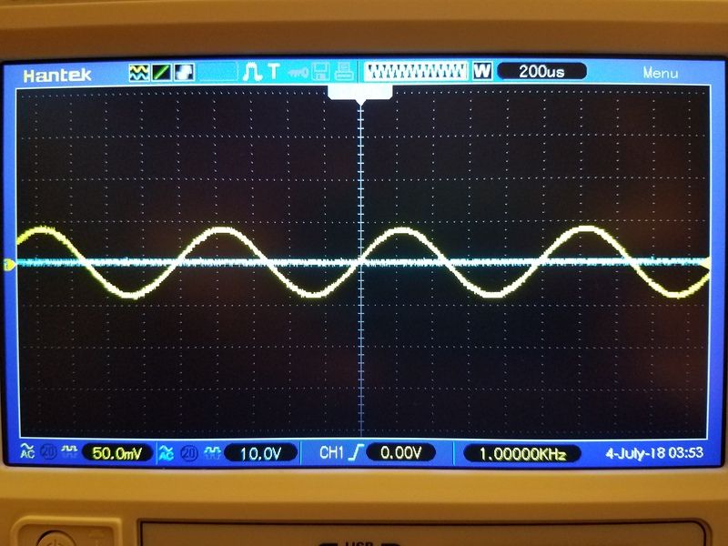
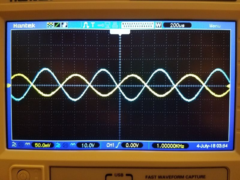
Volume on "5". Yellow input, blue output at jack.
Kuhhhh-ranked to 10.
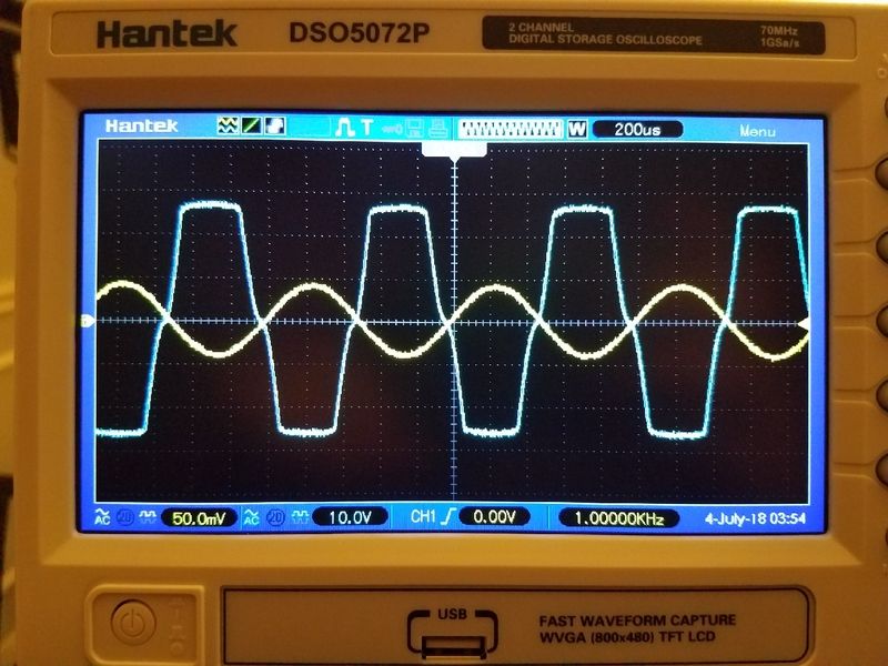
So, to me, in my n00b non-expert opinion of a guy just trying his luck, the signal looks pretty good. Nice and even, symmetrical, all that good stuff. So I don't know.Comment
-
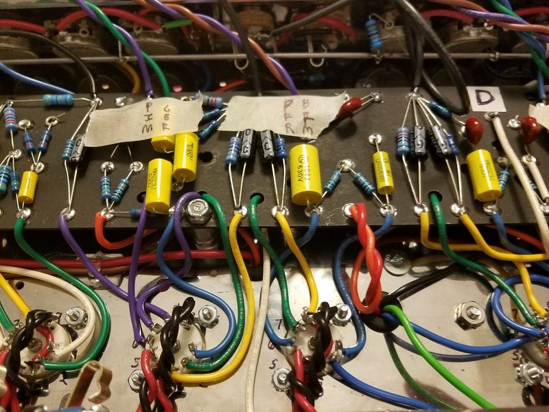
Oh brother, that is exactly the problem I had: (and your wiring is 6.02 x 10 ^23 times better than mine. Or more), reverb wiring was making the adjacent preamp wiring very angry. Very. I made the loop way shorter and put it on the other side of the tube, towards the back of teh chassis, and also, made sure that the reverb driver wiring did not run parallel to any of the adjacent preamp wiring. A feat for my 11 left thumbs, and 7 right thumbs. (significantly more difficult to diagnose without a scope as well). You also have two yellow wires, one leading to the reverb driver and one leading down someplace that are a little close and parallel. Try moving that back as well.Originally posted by Greg_L View PostThe only good solid state amp is a dead solid state amp. Unless it sounds really good, then its OK.Comment
-
Ha, yes mine was angry too.Originally posted by mikepukmel View Post
Thanks for the tips man.
Those yellow wires are both cathode wires. I will go in and start separating things a little better. The board layout in relation to the tube sockets makes it very difficult to keep things from crossing or getting to close to each other.Comment
-
There's a wire that runs from the cap board, through a grommet to the tube side of the eyelet board, up to an eyelet and joins with the wire runnning to the reverb transformer. How is that wire routed?The only good solid state amp is a dead solid state amp. Unless it sounds really good, then its OK.Comment
-
It's a pretty direct shot, and twisted with the reverb transformer wire. I did it this way so I can flip the board if need be.Originally posted by mikepukmel View Post
The red and orange twisted wires.
Comment
-
Just to re-iterate, I know close to nothing. I had huge help from the gurus on this great site to get my amp playable. That said, I had problems with the wiring to the reverb transformer, the loop around the reverb driver, and also parallel wires on a few of the tubes.
Im looking for a photo of my chassis for you to laugh at.
***
The photo sites like flickr and some others seem to be getting all "pay for this now" about linking to random photos. Anyway, I spent ages hunting down what I was fairly sure were period blackface amp chassis, the ones with really good lead dress. Lots of really good examples in those older amps. Some of the later 60's and early 70's amps, I have no idea how they worked at all.The only good solid state amp is a dead solid state amp. Unless it sounds really good, then its OK.Comment
-
Right? I too looked at tons of original examples, and I'm like, how the effin hell did these things work at all? I mean everyone screams from the rooftops about lead dress, meanwhile thousands of 50s and 60s Fender amps worked hard day and night looking like a blind 5 year old put them together. WTF?Originally posted by mikepukmel View Post
Comment
-
lead dress isn't about being pretty. There are some boutique builders who go out of their way to make all the wires in nice square corners, and lashed together, and solder joints all doped. Who cares?
What lead dress means is keeping your signal lines at 90 degree angles to wires carrying AC when they must cross. It means moving grid wires away from plate wires, and again, if they might interact, make them cross at more of an angle.
Lead dress often means routing something in as straight a path as possible. The super neat wire job where the wire goes off to one side then turns across the board and then back to a control just adds several inches to a wire that is sensitive.Education is what you're left with after you have forgotten what you have learned.Comment
-
Cool, thanks.Originally posted by Enzo View Post
Well one thing I've done is got the heater wires totally out of the way. I think I'm pretty good with that. The amp is very very quiet - quieter than any of my Marshalls. My heaters are crammed in the corner of the chassis and make a direct shot to and over the tube socket. My signal wires are all coming in from the sides. Some of them cross and that can't be avoided while trying to maintain a reasonably short route to the tubes.
But tomorrow I will try to separate and maybe re-route some of them better.Comment
-
So a few updates....
I think I have two things going on here - a little minor oscillation and the brittle noise that was the start of this whole thread.
First, the oscillation. I say "minor" oscillation because it doesn't freak out the scope or send the tubes into cutoff or anything, but it shows as little tiny kinks in the signal at various points in the amp. Maybe that isn't oscillation at all? I mostly notice these little sine wave deformities at the very peaks (top or bottom) of the signal and only when the amp is cranked or just shy of being cranked. And it's only in the vibrato channel.
Moving lead dress around has no effect. Besides the one plate jumper relocation on V3 I did earlier, no other wire jiggling or separating has made any difference. What does make a difference? The reverb tank. If I disconnect the reverb tank input, any abnormality in the scope display goes to perfectly normal. Any kink or hiccup in the sine wave goes smooth when I disconnect the reverb tank. What do yall think of that?
Second issue, the persistent brittle noise. Still stumped on this one. The amp otherwise sounds great and works great, it's just got that damn little sound hiding in the base tone and I want it gone if possible.
One more thing for now....is it weird that my output signal at the speaker jack is 180 out of phase with the input signal? I know the signal flips a few times as it travels throughout the amp. Am I just ending up with an odd number of signal flips and flops?Comment
-
What reverb tank? I mean the actual numbers.
Are both tank jacks grounded?
perhaps there is a ground loop thru the tank.If it ain't broke I'll fix it until it is...
I have just enough knowledge to be dangerous...Comment


Comment