 Tweet
Tweet
Scoping will tell us RF or not and answers many questions. Also tells us which direction to proceed.
-
Education is what you're left with after you have forgotten what you have learned. -
okay. I'll see what I can see.Originally posted by Enzo View PostIf I have a 50% chance of guessing the right answer, I guess wrong 80% of the time.Comment
-
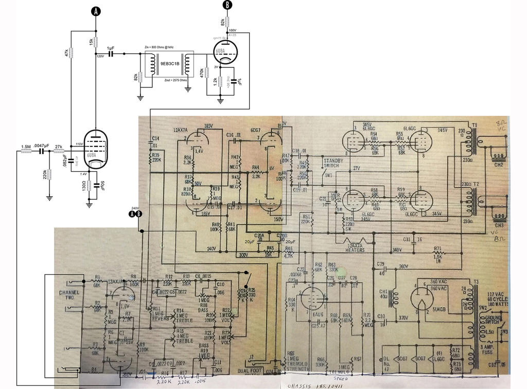
The original has a 68K resistor between the plate and the tank, so there is a good voltage swing. You are going straight into the tank, so the voltage swing is very small.Comment
-
I scoped the voltage at the outgoing terminal at the junction of the 82k/1uF cap and there was plenty of signal there, but I guess I don't understand how that would be contributing to my problem? Could you elaborate?Originally posted by 66 Kicks View PostIf I have a 50% chance of guessing the right answer, I guess wrong 80% of the time.Comment
-
With the tank connected, the voltage swing at the 6U8A driver plate varies wildly with frequency. At the pesky resonant frequency the voltage swing is practically nothing. It is never much more than a few volts with the guitar frequencies used.Originally posted by SoulFetish View Post
The driver output cannot be used in the dry signal path.Comment
-
Ah, I see what you mean now. That makes sense and would explain why I'm getting the voltage loss. Plus, when I was looking at the output terminal on the scope, I believe the tank was disconnected. I will tap the dry signal from another node.Originally posted by 66 Kicks View Post
hmmm..... Im doubting the input stage can drive both the pentode and tone stack in the dry signal path. ughIf I have a 50% chance of guessing the right answer, I guess wrong 80% of the time.Comment
-
I know what I'm going to do. best part is should be a minor change with few added parts! I'll draw it up after work.If I have a 50% chance of guessing the right answer, I guess wrong 80% of the time.Comment
-
I'm going to use the normal, channel 2 input stage as the dry signal and install a switchcraft switching jack on channel 1. I can then run a parallel wire from the input of channel 2, to the switch part of the jack on channel one. That way, when channel one is unused and closed, I can use that triode stage to provide the input signal to the Pentode driver.
As follows:
I also decoupled the 6U8A stages with a dropper/20�F capacitor and added another 10�F filter to the channel mixing/cathodyne stages.If I have a 50% chance of guessing the right answer, I guess wrong 80% of the time.Comment
-
So, I finally got back to this after a few weeks and finished up the amp.
The goal was to add the 6U8A reverb circuit and integrate it into his stock amp, disturbing as little to the interface and operation of the amp as possible. To be honest, the design of the driver and recovery input were pretty easy, and you all were super helpful checking my work giving me some great direction. It definitely needed it's own dropper and filter node to stabilize the operation and remove power supply ripple from the amp, and I isolated the dual input stage with a it's own 10�F cap.
But, by far, the most challenging part was/is designing the recovery/return stage and mixer. I'm trying so hard not to mess with the rest of it because it sounds so good now. But, even with a gain of +31dB in the recovery amp, still only looking at around 165mV. Ugh, I'm like one inverting gain stage away from nailing this and I've looked everywhere in the amp to try and fake it, but then I end up with the two input channels out of phase. I'm actually glad I decided to do this project, I'm learning a lot about signal mixing that I didn't realize I didn't even know. For instance, an obvious condition of this amplifier was heavy interaction between channel controls even when the channel was not being "used". I totally get it now and seems obvious seeing the loading on the driving impedance, and the compromises which sometimes need to be made between noise, gain, and channel isolation when using passive mixing.
Even so, as it stands right now, I decided to mix it at the 12AX7 grid of the second stage where the two channels sum. It sounds pretty good too
But it really could be great.(Oh, Nick, I think I'm going to take you up on the suggestion of adding that parallel 5k1 resistor across the coil. I'm getting a touch of instability, almost like a ringing in a microphonic tube at higher frequencies. Not bad, but needs to be dealt with.) I feel like I can achieve better results by padding the dry signals, and even better still if I add inverting feedback. But, then I'm sacrificing gain that I've really become attached to. There's a couple of options I'm thinking about to address the need for higher gain in the recovery.
#1- use one of the 12AX7 triodes from one of the channel inputs and use the low/med mu 6U8A triode as a low gain input. This effectively doubles the voltage gain of the reverb recovery amp.
#2- Use a JFET/Triode hybrid cascode as the recovery amplifier. Now, if this sounds familiar. Perhaps you caught the wildly popular thread that was burning up the Theory and Design section just recently. Super helpful.... :/
it's okay though. I was able to learn how to do it, so if any of y'all need to know what to do. I'd be happy to give ya a heads up on it. This is even better than using the 12AX7, as it gives me the potential for much greater gain out of the single stage. I'll probably do this.
#3- Install a whole. nutha'. tube. That's right. Turns out that the 6CG7 draws +/- 600mA of heater current and was one was replaced by the 6U8, which draws around 420mA. This gives me some available supply for another 12AX7 run at 6.3V, or I can run the heaters in parallel with one of the other 12AX7s which draw from the B+ as par of the bias supply. This would give me so many different options. Hell, I only need one of them for to give us reverb for days. The other one I could use as a unity gain virtual earth mixer for the two channels. Wouldn't that be something. Listen,... you guys hear that? it's proper channel isolation.
The rest of the amp took a lot of work, but it is now a rock and roll machine and it sounds absolutely killer. I only made a few changes to recover a little bit of gain by driving both channels when two instruments aren't plugged in other minor tweaks. Also added a couple of components to stabilize the Phase Inverter and drivers. But I've never heard a silvertone overdrive like this one does now. I'll try and get some clips of how it sounds to share.If I have a 50% chance of guessing the right answer, I guess wrong 80% of the time.Comment
-
Interesting to note: I found some JFETs among my stock of semiconductors. 2 happen to be sealed NTE459s. Here is the datasheet. No curves, but do you guys think this would be suitable to be the common source input of the cascode?
NTE459.pdf
If not, I found a US distributor of LSK170s. I may order a handful of these anyway to have.
https://store.nacsemi.com/products/d...IS000000001338If I have a 50% chance of guessing the right answer, I guess wrong 80% of the time.Comment
-
Well I for one thought the JFET was a jolly good idea you deserve all credit for thinking of it. I expect the other thread didn't take off due to lack of familiarity. Loudthud has done a lot of work with JFETs and i bet he could chip in an idea or two.
A problem with JFETs is the datasheets are often lacking. DC parameters have a wide spread and noise figures are seldom quoted. The one you have might well work - the spread of Idss is huge on the datasheet. You need to get at least a volt of bias to give enough headroom for a decent pickup. I think you have to shove a few devices in there are find one that biases up where you want. A bit of source degeneration will be desirable to keep the gain the a reasonable level. I haven't looked at the plate curves of the tube you are using. Will it have enough voltage at the cathode (drain) to ensure the FET is in the saturation region? I think just about any JFET that you get to work will outperform the current arrangement.
Nice to hear that it's sounding good!Last edited by nickb; 10-18-2018, 07:08 AM.Experience is something you get, just after you really needed it.Comment
-
Yeah, if I understand it correctly. If you look at the original schematic of the amp, the 2 12AX7 heaters connected in series and form part of the cathode bias of the 6L6s. I was going to tap off at the 12V junction to provide the effective g2 voltage of the triode section. this will put me well into the saturation region of the FET. Changing the original 82k plate load to 47k looks like the load goes through the knee of the 0Vgk curve. (Still a little strange that the upper tube is at 0 Vgk.) I'll probably do a little more digging into some datasheets as well, but I may end up going with an LSK170. I have much more data to use and it's beloved for it's low noise. Assuming that choice, a source resistor of around 130Ω gives me a lower bias of -.3V, dropping the anode of the triode to around 100V.Originally posted by nickb View Post
Everything sound about right?
I also saw a handfull of 2N545-somethings as well those NTE549s, so I can even set up a little test rig and so some experimenting.If I have a 50% chance of guessing the right answer, I guess wrong 80% of the time.Comment
-
This project and design have are almost complete,... I promise. Here is how everything turned out.
The cascode recovery amp has significantly more gain and allows me to mix the wet signal at the junction right before the tone stack. The increase in gain was causing massive instability at the previous mixing point. But the current mixing location was the initial design goal anyway, and subjectively sounds much better. In fact, the amp sounds almost incredible. I love the reverb tone and decay, and plan to experiment a little with the divider ratio to see what I can get away with. I just finished wiring in up so I want to really put this through the paces tomorrow.
The other changes, which could be done independently of the reverb, really opened this amp up. Really responsive overdrive and there's plenty of it.
I'll be sure to record some proper samples to share, but there is an issue that needs to be fixed before I can do that.
I'm getting a significant amount noise which sounds like 60 cycle hum, but i'm concerned that I may have brought out a ground loop. The original ground scheme is not great, and there is a lack of available space and terminals isolated from the chassis to work with as tie points in this amp. I probably would have been better off stripping everything out and doing a scratch build at this point. But I've isolated Where the problem seems to be coming from.
There is a half of a 12AX7 which acts as a summing input and recovery gain stage for the two channels, which drives the second triode which is a cathodyne phase inverter. If I lift the cathode of the summing triode, the amp is quiet as can be. you wouldn't even know its on. The video noise was recorded with all the channel controls turned completely down. The volume controls do have some effect on the increasing the background noise, but has really no control other than that. The reverb tank is not connected during this short clip as well.
Here is the current schematic:

and the video:
ground loop-60Hz Hum.mov.zip
I've tried new tubes and they all seem to be really touchy in this spot. Here is another weird thing, if I shine my led headlamp on that tube, they squeel? weird.
So, you guys have any thoughts?If I have a 50% chance of guessing the right answer, I guess wrong 80% of the time.Comment
-
You are deriving the grid potential (12V) of the recovery triode from the cathode network of the power tubes. I don't think this is a good idea, as the cathode voltage is not constant at large-signal operation. Also the ripple filtering at this point may not be good enough. May even contain some 60Hz heater hum, especially as the cathode bypass cap is rather low capacitance at 10�.
Why don't you use a voltage divider from node B and if necessary an additional filter cap across the low-side resistor?
The grid supply must be particularly clean, as the grid is still an input and any tiny ripple content gets amplified by the tube.Last edited by Helmholtz; 12-07-2018, 02:38 PM.- Own Opinions Only -Comment
-
@SoulFetish:
Thanks for your Thumbs-up.
I hope no-one ever gives me rep points instead of thumbs. I have no use for them and don't like that they are anonymous. I like real feedback and thumbs show me that my advice was well understood and received.- Own Opinions Only -Comment
Comment