 Tweet
Tweet
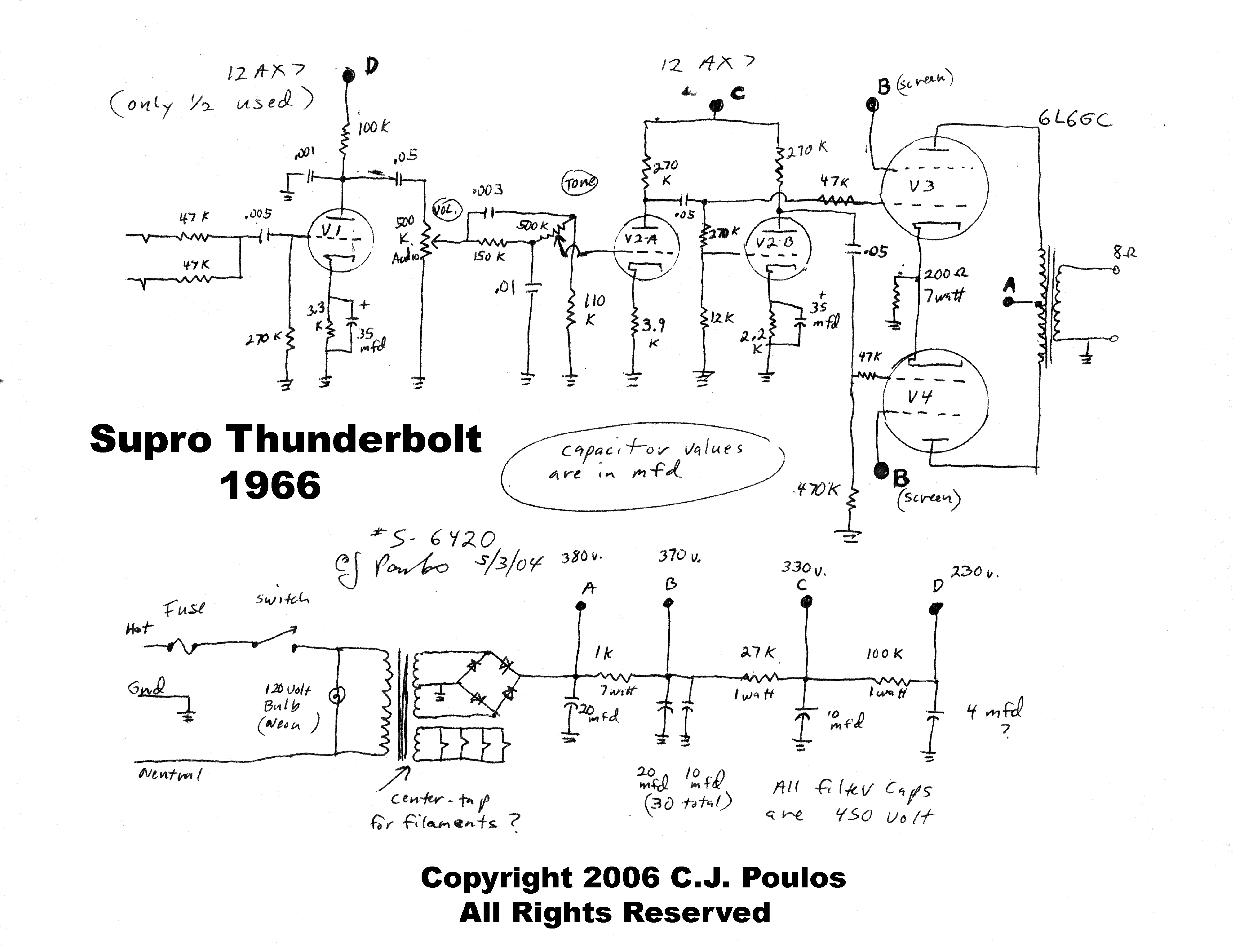
Pulling my hair out to try to figure out how this amp would work without shorting the PT secondary. Going back and forth between the various versions of this amp schematic, I think the CT should not be grounded. Wouldn't it provide a path to a dead short across one diode, depending on which half cycle?
"It must be right, is on the internet"
"It must be right, is on the internet"


Comment