Announcement

Collapse
No announcement yet.

Screaming Bright Switch Cap??? - 1974 Fender SF Twin Reverb Master Volume Push Pull Switch

Collapse
X
 
  • Filter
  • Time
  • Show
Clear All
new posts

  • Originally posted by Helmholtz View Post
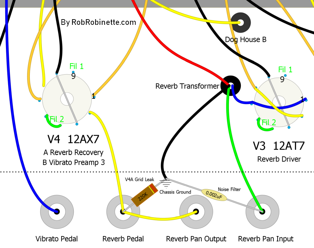
    Do you use the .002µ cap at the reverb return?
    Nope, it's still at the Reverb INPUT as described here below. The reason is that to my ear (way before we added the 560 pF cap or the voltage divider, the amp sounded better (not speaking about the REVERB but the DRY sound with the REVERB tank connected to the amp) with the cap in this position than on the REVERB OUTPUT. I remember you said in the past it would make the reverb sound "darker". I can try to connect it to the REVERB OUTPUT.

    Comment


    • I can try to connect it to the REVERB OUTPUT.
      Please do this first. It is probably the most promising measure to increase reverb treble. A capacitor at the secondary of the reverb transformer has a similar effect as a capacitor across the primary (as you have).

      Please understand that (partly) successful modifications are not necessarily independent and additive regarding their effects.
      - Own Opinions Only -

      Comment


      • mache ich sofort / right away

        thank you for pointing that out. and I will take the chance to re-clean all the star washers and re-do the long overdue soldering in that area (there was a lot of trial and error in that part of the circuit in the past).

        Comment


        • well... did the homework

          first I de-soldered everything that was connected to the RCA REVERB Jacks, cleaned, sanded and re-soldered.


          I believe it looks better

          What I am holding in the center photo (red background) is the way I put the RCA jacks back: start washer against the chassis, the ground ring in the middle and another star washer in contact with the jack (it wasn't like that when I got it, but I believe it makes sense to do it like this)

          Second, when re-soldering the components back I have changed the .002 uF ceramic cap from the REVERB INPUT to the REVERB OUTPUT.

          Result: the REVERB wet signal it's a bit brighter. Which helps giving the impression that it is also louder, however after some listening I do not think it is the case. To give you an idea, I think the REVERB sounds as if the REVERB VOLUME was at 4.

          I am very happy with the improvements (don't think I am an ungrateful b*****) and with what I am learning. Thank you again everyone who has contributed in these 300+ posts.

          My question:

          Chuck, I know you have advised it not to be the best solution, however I see at Rob Robinette's page he suggests changing the value of what he calls the "470K Reverb Attenuation Resistor" to increase the amount of WET REVERB signal. From what I understood in your post, your view is that it is actually decreasing the DRY SIGNAL and thus reducing the overall VOLUME and not actually increasing the amount of REVERB WET signal. Do you mind taking a look at it?

          The main statement is: "At the output of the Reverb circuit the wet reverb signal flows through the Reverb pot, then through a 470k Reverb Attenuation resistor that forms a voltage divider with the following V4B (3rd stage preamp) 220k Grid Leak resistor and dumps 68% of the wet reverb signal to ground. You can tweak the reverb output level by changing the 470k Reverb Attenuation resistor. To increase the max reverb level replace it with a 220k and the attenuation drops to 50% and 110k will give 33% attenuation. Replacing the resistor with a jumper (or bypassing the resistor) will give 0% attenuation"

          The description is halfway through the page and titled: Adjust Reverb Level Mod
          https://robrobinette.com/AB763_Modif...verb_Boost_Mod

          NOTE: this mod is under the AB763 and I basically want to know if it should work on my amp. As a reminder, there was a 220 K resistor in lieu of the stock 470 K originally (though I am not saying it was "original" from the factory). I remember more reverb, however back then I did not really pay attention to it being MORE REVERB or LESS DRY signal.
          Last edited by TelRay; 09-04-2019, 12:38 AM.

          Comment


          • Originally posted by TelRay View Post
            Chuck, I know you have advised it not to be the best solution, however I see at Rob Robinette's page he suggests changing the value of what he calls the "470K Reverb Attenuation Resistor" to increase the amount of WET REVERB signal. From what I understood in your post, your view is that it is actually decreasing the DRY SIGNAL and thus reducing the overall VOLUME and not actually increasing the amount of REVERB WET signal. Do you mind taking a look at it?
            Ok... I did some actual spice simulations and the results confirm what I posted above. With the caveat that it's not that the reverb signal DOESN'T increase. It does. But the decrease in dry signal is greater. And the ratio gets worse depending on how much you decrease the "reverb attenuation" resistor.

            Two things must be clarified. First, we love Rob. His page has been reasonably consistent and of tremendous help to a lot of people wading into this genre. This is a rare miss for him though. There are others too, but it's never anything major so we tend to let it go here on this forum. But in this instance his pages advice could be as much detriment as help. We can do better.

            Second,.. It has to be noted that a typical BF amp, which Rob's advice applies to, has a 220k load resistor following the 470k "reverb attenuation" resistor. Your amp uses a 470k load following the 470k "reverb attenuation" resistor. This load makes a significant difference in how the shared loads between the wet and dry signals works. Roughly halving Rob's intentions for changes to that resistor value both in increasing the reverb signal and detriment to the dry signal for your specific amp. So, basically, Rob's advice doesn't directly apply to your amp. And IMHO is less than good even as it applies to the BF type circuits. JM2C. BUT...

            The resistances in the dry/reverb mixing circuits absolutely can be manipulated to improve reverb volume without detriment to the dry signal strength or tone. It requires a more extensive modification though. You'll probably need to order parts (your patience would be rewarded).

            It's my opinion that increasing the signal to the reverb driver tube could also be beneficial. I'm glad that your efforts to mitigate the odd oscillation have worked, but edging up the drive to the reverb tube so that it's as high as possible without instigating the problem would be best. Reverb tanks sound best when driven to the highest level prior to distortion. Limiting drive to the tank changes the "nature" of the reverberation. In my experience it's best to drive the tank more than less (short of transducer saturation) for tonal quality. So I think it might be a good idea to experiment with how much you can increase drive to the reverb without instigating the tonal anomaly.

            There are no R#'s in the schematic you've been using so I hope you can identify the components I'm about to discuss. Here's the mod:

            1) change the 3.3M resistor to 2.2M

            2) Change the capacitor across it to 15P

            3) Change the "reverb attenuation" resistor to 180k

            4) Change the 470k load resistor off the "reverb attenuation" resistor to 1 Meg

            This would leave your dry signal very close to where it is now, but increase reverb/dry signal ratio such that the reverb signal is about 5dB higher than it is now.

            Increasing brightness in the reverb is trickier. You could experiment with a parallel capacitor across the reverb drive voltage divider series resistor. But that may reintroduce the oscillation. You could reduce the value of the reverb recovery stage cathode bypass capacitor to something like 100n. But that only limits LF and would reduce reverb volume yet again, but leave the HF at the higher level.

            So this may require some fine tuning. This is sort of what I do I'm having a little fun I suppose.
            "Take two placebos, works twice as well." Enzo

            "Now get off my lawn with your silicooties and boom-chucka speakers and computers masquerading as amplifiers" Justin Thomas

            "If you're not interested in opinions and the experience of others, why even start a thread?
            You can't just expect consent." Helmholtz

            Comment


            • thank you, Chuck! another great reply.

              I saw the circuit description being different to mine and the lack of the 200 K resistor but... as there was a “reverb attenuation resistor” of 220 K instead of the 470 K when I got the amp I thought maybe that was a solution someone applied for a good reason. However, after your explanation it’s clear someone before me already made this mistake (good knows how many hands has this poor thing passed through)

              What I am reading also is that before trying to increase the REVERB WET signal in the mix I should try to drive the tank as hard as possible without triggering the anomaly we are fighting against here.
              That is, the resistor values at the voltage divider.
              - no voltage divider (1M/0 Ohm) -> anomaly
              - 500 K / 500 K -> anomaly
              - 250 K / 750 K -> OK
              Now, I should try combinations like:
              -400 K / 600 K
              - 300 K / 700 K
              see what sounds good and AFTER that, proceed with your “recipe” if the reverb volume is still low.

              Sometime I wish we could kill the real root cause of this, but detection has been a real hard one.

              thx!!!

              Comment


              • I guess I'm not committing all the info so far to memory, and not re reading the entire thread before my replies. If you've already stepped the voltage divider before the reverb drive to 500k/500k before trying the 750k/250k combo then I'd say you've practiced due diligence on the matter. Not much to be gained working between 500/500 and 750/250.

                As to the root cause, I can't help thinking there might be something hinky about your reverb transformer. My reason isn't great, but I've heard something like your problem with the amp in other amps that had a bad reverb cable or tank, and therefor no load on the transformer secondary. I think I mentioned this early on in the thread but it just sort of hit the floor without even bouncing.

                As it happens, because you already have a 200k resistor in place for the "reverb attenuation" resistor there isn't much to be gained by making the changes I proposed above. The changes would return the dry signal to it's stock level about 5dB greater than it is now (thereby increasing the dry to wet ratio and making the reverb smaller) and only increase the reverb by about 1.5dB. Which is probably not enough to notice. So don't trouble with it.

                Other than my comment regarding possible problems with the transformer I can only suspect lead dress or grounding, as has already been discussed and some efforts have been made, and possibly layout. Like the actual location of the reverb transformer. You might try flipping it 180*. While you have it removed you could test it for relative goodness too. What do you have to lose?
                "Take two placebos, works twice as well." Enzo

                "Now get off my lawn with your silicooties and boom-chucka speakers and computers masquerading as amplifiers" Justin Thomas

                "If you're not interested in opinions and the experience of others, why even start a thread?
                You can't just expect consent." Helmholtz

                Comment


                • Now, I should try combinations like:
                  -400 K / 600 K
                  - 300 K / 700 K
                  The higher the upper (series) resistor value of the voltage divider, the more reverb treble will be lost. You might try 330k/500k. The sum value doesn't have to be exactly 1M.
                  Last edited by Helmholtz; 09-04-2019, 01:43 PM.
                  - Own Opinions Only -

                  Comment


                  • This could be significant because the 560k/1.5k shunt across the reverb transformer primary really doesn't dull the reverb tone significantly. It only demonstrates a 1dB attenuation at 10k!!! (assuming a typical 22k primary impedance on the reverb transformer) So the dulling of the reverb must be happening as a result of the input voltage division and/or how the tank is responding to the drive level.

                    You could try a low value capacitor across the 750k input series resistor. I have a hunch this might bring back the oscillation though. Something like 30pf or 47pf I would think. Just enough to sparkle
                    "Take two placebos, works twice as well." Enzo

                    "Now get off my lawn with your silicooties and boom-chucka speakers and computers masquerading as amplifiers" Justin Thomas

                    "If you're not interested in opinions and the experience of others, why even start a thread?
                    You can't just expect consent." Helmholtz

                    Comment


                    • So the dulling of the reverb must be happening as a result of the input voltage division and/or how the tank is responding to the drive level.
                      I meanwhile think that the typical Fender reverb sound at least partly depends on overdriving the reverb driver tube. Overdrive causes additional higher harmonics, but the tank's transfer response somewhat smoothes out the distortion.
                      Now the voltage divider reduces the reverb driver distortion (as intended) but the additional harmonics are missing.

                      Partly redesigning an existing amp often means compromising...

                      BTW, I still wonder how the oscillation manages to get across the pond (reverb tank), as the springs won't be able to transfer such very high frequency. Just like you I suspect some capacitive coupling in the squeezed wiring or coupling via the power supply. The latter possibility I would try to eliminate first. There must be no traces of oscillation on supply voltages.
                      Last edited by Helmholtz; 09-04-2019, 03:01 PM.
                      - Own Opinions Only -

                      Comment


                      • Originally posted by Chuck H View Post
                        ...because you already have a 200k resistor in place for the "reverb attenuation" resistor there isn't much to be gained by making the changes I proposed above. The changes would return the dry signal to it's stock level about 5dB greater than it is now (thereby increasing the dry to wet ratio and making the reverb smaller) and only increase the reverb by about 1.5dB. Which is probably not enough to notice. So don't trouble with it.
                        thx, man...
                        further clarification on this. I had a 220 K resistor on the "reverb attenuation when I bought the amp. As I reverted it to the schematics, I put a 470 K resistor that's been there for many moons even before starting this (very long, educational and productive) thread.
                        So, today the reverb attenuation is a 470 K resistor.
                        So, I think all the modifications you've proposed are relevant. Do you agree?

                        I agree on checking the REVERB Transformer 100%, G1 has mentioned that as well (polarity, etc). I just don't know how to test it. However I could learn.

                        Originally posted by Helmholtz View Post
                        The higher the upper (series) resistor value of the voltage divider, the more reverb treble will be lost. You might try 330k/500k. The sum value doesn't have to be exactly 1M.
                        Ahhhh... wunderbar! Dass wusste Ich nicht!!!
                        I was always trying to reach the (original) 1 M Ohm value

                        Comment


                        • Originally posted by TelRay View Post
                          So, I think all the modifications you've proposed are relevant. Do you agree?
                          Yes. Do them. Free reverb volume. Giving you more room for correcting the tone of the reverb.

                          Originally posted by TelRay View Post
                          I agree on checking the REVERB Transformer 100%, G1 has mentioned that as well (polarity, etc). I just don't know how to test it. However I could learn.
                          Polarity is typically blue lead to the plates of the 12at7, green lead to the send jack, red lead to HV and black to ground. However, it's not unusual for transformer lead colors to be off. Especially WRT phase.

                          I'm considering basic tests to detect shorts and determine if the ratio is correct. These aren't hard to do and you already have the tools. We can cover it when/if it comes up.

                          I'm also considering the physical phase/orientation of the reverb transformer. It may or may not make a difference.
                          "Take two placebos, works twice as well." Enzo

                          "Now get off my lawn with your silicooties and boom-chucka speakers and computers masquerading as amplifiers" Justin Thomas

                          "If you're not interested in opinions and the experience of others, why even start a thread?
                          You can't just expect consent." Helmholtz

                          Comment


                          • Alright people! It seems I have a little bit of work ahead Here listed all the proposals discussed in the last days:

                            1.- CHANGE RESISTOR VALUES ON THE ADDED VOLTAGE DIVIDER:


                            The amp has currently installed TRIAL 2 and TRIAL 3 is what Herr HELMHOLTZ has just proposed.

                            NOTE: so far, when I say RESULT OK or KO that is regarding the ANOMALY (higher harmonics / oscillation). Not speaking about the REVERB VOLUME and TONE yet (as the REVERB TANK was disconnected in the past to avoid the ANOMALY until TRIAL 2)


                            2.- KEEP OR REMOVE THE ADDED 5 K RESISTOR IN SERIES WITH 560 pF CAPACITOR:

                            Originally posted by Chuck H View Post
                            This could be significant because the 560k/1.5k shunt across the reverb transformer primary really doesn't dull the reverb tone significantly. It only demonstrates a 1dB attenuation at 10k!!! (assuming a typical 22k primary impedance on the reverb transformer) So the dulling of the reverb must be happening as a result of the input voltage division and/or how the tank is responding to the drive level.
                            You could try a low value capacitor across the 750k input series resistor. I have a hunch this might bring back the oscillation though. Something like 30pf or 47pf I would think. Just enough to sparkle
                            You mean 560 pF / 1.5 K, right?
                            As highlighted in RED above that 1.5 K resistor was changed to 5 K to try to (as we said) make the 560 pF capacitor less efficient in killing the higher frequencies and recover some highs on the WET REVERB signal
                            should I completely remove that resistor from the circuit?
                            NOTE: there's no resistor in the original schematic


                            3.- INCREASE REVERB BRIGHTNESS:

                            Originally posted by Chuck H View Post
                            You could try a low value capacitor across the 750k input series resistor. I have a hunch this might bring back the oscillation though. Something like 30pf or 47pf I would think. Just enough to sparkle
                            By 750 K resistor you mean the one that has evolved from 0 Ohm to 500 K, 835 K and now is being suggested to be brought back to 500 K again?

                            This...


                            4.- MODIFY THE REVERB WET SIGNAL MIX:

                            Originally posted by Chuck H View Post
                            There are no R#'s in the schematic you've been using so I hope you can identify the components I'm about to discuss. Here's the mod:

                            1) change the 3.3M resistor to 2.2M
                            2) Change the capacitor across it to 15P
                            3) Change the "reverb attenuation" resistor to 180k
                            4) Change the 470k load resistor off the "reverb attenuation" resistor to 1 Meg
                            I think I got the mod right


                            QUESTION:
                            What sequence would you recommend?

                            I am thinking:

                            1.- Change values on voltage divider as it increases the drive of the reverb and should increase volume and brightness
                            depending on the VOLUME or BRIGHTNESS increase
                            3.- Increase brightness or 4.- modify reverb wet mix
                            2.- to be decided
                            Last edited by TelRay; 09-04-2019, 10:24 PM.

                            Comment


                            • A 1M trimmer could be tweaked to find the optimum compromise https://www.newark.com/bourns/3386p-...201m%20trimmer
                              My band:- http://www.youtube.com/user/RedwingBand

                              Comment


                              • Originally posted by pdf64 View Post
                                A 1M trimmer could be tweaked to find the optimum compromise
                                thank you for the suggestion, I believe that applies to "1.- CHANGE RESISTOR VALUES ON THE ADDED VOLTAGE DIVIDER:". Are you suggesting one trimmer on the series resistor or 2 trimmers and play with both values?

                                Comment

                                Working...
                                X