Announcement

Collapse
No announcement yet.

Gretsch (Valco) 6156 - Phase Invertor, What is it ?

Collapse
X
 
  • Filter
  • Time
  • Show
Clear All
new posts

  • Gretsch (Valco) 6156 - Phase Invertor, What is it ?

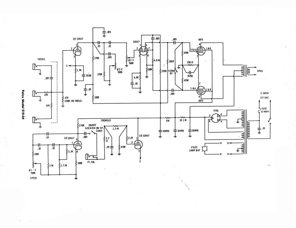
    I have a Gretsch 6156 that uses a different type of phase inverter than I am accustomed to (paraphrase).

    Can anyone describe what they are doing in the below schematic ? I think it's a 'Type' of Cathodyne PI arrangement, but it seems like something else as well. The amp sounds fantastic, particularly after I increased the size of the power tube coupling caps from .005uf to .022uf, and the PI cathode Bypass cap from .05uf to 1uf (this added some needed Bass to the 12" Jensen), and the amp still sounds very clear and crisp, even in high gain clean boosted signal up-front.

    Thanks in advance for any help !

    Last edited by HaroldBrooks; 03-29-2019, 06:28 PM.
    " Things change, not always for the better. " - Leo_Gnardo

  • #2
    Thanks for sharing this Gretsch amp! Between this and the tone stack thread, I'm learning much about thinking outside the box!

    Now to business: the last valve is a fairly typical recovery stage followed by a cathodyne PI. What's curious about the PI is that they chose to use grid-leak-bias with that 6.8M resistor instead of what we commonly use now with a 1M leak and a 1k (ish) cathode bias resistor. Saving on parts count?

    I'm starting to think the designers drew out their circuits in such a strange way because they wanted to confuse the competitors, or maybe because they were just bored and high on reefer.
    Redrawing the circuits in a more conventional way reveals their similarity to circuits we are all familiar with.
    If it still won't get loud enough, it's probably broken. - Steve Conner
    If the thing works, stop fixing it. - Enzo
    We need more chaos in music, in art... I'm here to make it. - Justin Thomas
    MANY things in human experience can be easily differentiated, yet *impossible* to express as a measurement. - Juan Fahey

    Comment


    • #3
      Yes, the input is a bummer. Designed for a trio?

      Click image for larger version

Name:	scribble.png
Views:	1
Size:	455.3 KB
ID:	853532

      This is what I see at the PI, unrolled. Some unconventional values, but other than a grid-leak-bias pretty common.
      If it still won't get loud enough, it's probably broken. - Steve Conner
      If the thing works, stop fixing it. - Enzo
      We need more chaos in music, in art... I'm here to make it. - Justin Thomas
      MANY things in human experience can be easily differentiated, yet *impossible* to express as a measurement. - Juan Fahey

      Comment


      • #4
        Yes, its a cathode gain stage followed by a Concertina (aka split-load) PI employing grid leak bias.
        - Own Opinions Only -

        Comment


        • #5
          Here's the schematic without the giant photobucket logo:

          Click image for larger version

Name:	valco_510-54.jpg
Views:	1
Size:	624.7 KB
ID:	853533

          ...and, just for fun, an older version of the Gretsch 6155/6156 with octal preamp tubes, 6V6 outputs, and a field-coil speaker:

          gretsch_g6156.pdf
          Last edited by AttachMan; 03-29-2019, 10:01 PM.

          Comment


          • #6
            Typo? Where is it getting plate voltages for in the gretsch_g6156.pdf?

            Comment


            • #7
              On that Gretsch_G6156 schematic, did you notice that the right-half triode of the 6SC7 has NO cathode connection -- nothing connecting the two cathodes together. Obviously a drawing error, or the amp wouldn't work.

              Addendum: Checked the 6SC7 tube data and it has a SINGLE common cathode, so the schematic drawing is in error, because the cathodes ARE actually internally tied together, so single, wide, cathode should've been drawn.
              Last edited by Old Tele man; 03-29-2019, 11:07 PM.
              ...and the Devil said: "...yes, but it's a DRY heat!"

              Comment


              • #8
                Originally posted by mozz View Post
                Typo? Where is it getting plate voltages for in the gretsch_g6156.pdf?
                Through the field coil?

                Comment


                • #9
                  Back then it was known the 6sc7 had a single cathode connection. But if you look at the input triode plate and the 6sc7 second plate, there is no voltage? I think the one jumper should actually be a connection.

                  Comment


                  • #10
                    Originally posted by mozz View Post
                    Back then it was known the 6sc7 had a single cathode connection. But if you look at the input triode plate and the 6sc7 second plate, there is no voltage? I think the one jumper should actually be a connection.
                    I think you're right. An easy mistake to make.

                    Comment


                    • #11
                      Thanks for everyone's input so far ! So I take it that the PI is some type of Hybrid Cathodyne and Grid Leak Bias setup ? Also, not sure why Gretsch would put such an awfully small cathode bypass cap on the first leg of the PI 12AX7. Is there a reason for this, other than wanting to boost treble further ? I put a 1uf in it's place, and it enhanced gain, Lower midrange, and bass and made the amp much warmer and bigger sounding in the process. As to the 47K grid to ground resistor on V1, I changed that initially to 470K, and it introduce a boatload more of gain, but also hum. The tone also changed as I think the Preamp 12AX7 was clipping very early as a result. I took a hint from the original schematic that stated some other variation of the 6156 get's a 100k resistor, and that worked to increase input gain a bit, not introduce any significant hum, and maintain most of the original tonal balance. I also changed the Treble input cap from the stock .005uf to a .01uf so the input will still remain useful as a high pass filter (owning to the change in the ground resistor to 100k).

                      All in all, the amp is great, still I am in the Dark though as to how that PI arrangement works (including the grid leak).

                      Any other ideas ? Thanks !!!
                      " Things change, not always for the better. " - Leo_Gnardo

                      Comment


                      • #12
                        Big plate resistor total on V1a, you can lower those resistors and try the 470k input again? Lot of times you get hum if there is no bypass cap, or very small cap. I forget the reasoning you get hum but maybe could be a slightly leaky tube?

                        Comment


                        • #13
                          I am in the Dark though as to how that PI arrangement works (including the grid leak).
                          See:
                          http://www.valvewizard.co.uk/cathodyne.html

                          http://www.valvewizard.co.uk/Common_Gain_Stage.pdf (page 12)


                          Get the complete book, it's excellent!
                          Last edited by Helmholtz; 03-30-2019, 09:57 PM.
                          - Own Opinions Only -

                          Comment

                          Working...
                          X