 Tweet
Tweet
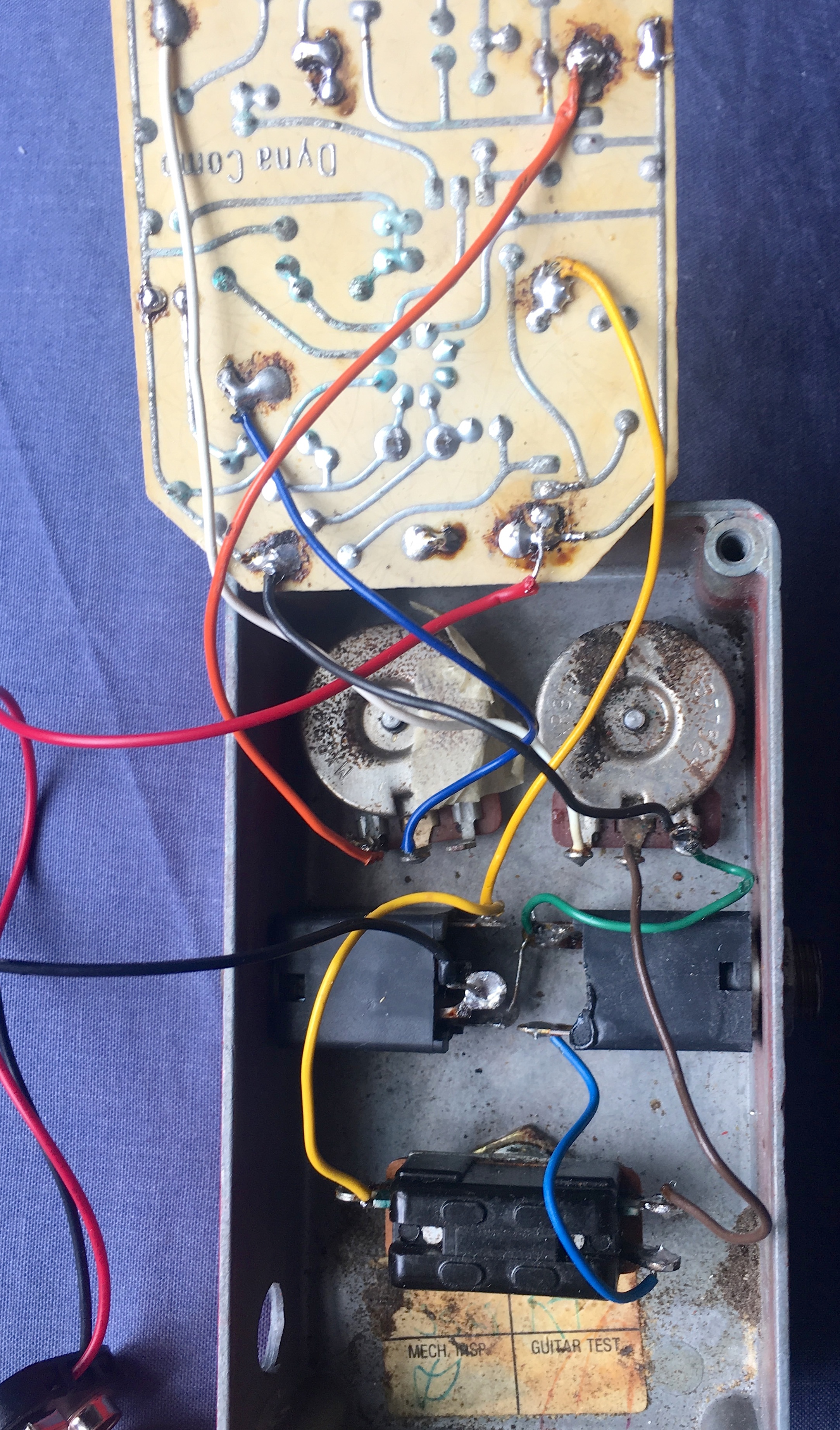
I have a 1970s script logo MXR Dyna Comp that I can't get working.
I bought it a few years ago and it was working fine, though at some point someone has drilled a hole in the side to fit a DC socket though not completed the job.
So I thought I would add that mod and also convert it to true bypass.
Sadly, due to weak solder joints some of the connections came adrift - I found online resources that led me to where they should be connected but I couldn't get the thing working.
At this stage I thought the best thing would be to return it to standard - it still didn't work and it's been sitting on my shelf gathering dust ever since.
Until today when I decided it was way past time to fix it.
Several hours of research (I couldn't find one clear set of photos to show where every connection should be) and numerous attempts at re-connecting and checking for bad solder joints and I'm still at a loss!
This is the fault description
When the pedal is switched out I get signal through.
When the pedal is switched on I get no through signal whatsoever - no buzz, or hum, or crunches if I move any of the wires around to check connections.
So I wonder if there is either a dead component or I've just made a mistake with my connections due to not being able to find clear enough photos to copy.
So here I am begging assistance.
I must make clear that I am not an electronic engineer - I can't even read a schematic - but I can follow clear graphic instructions.
I've uploaded two gut shots that, hopefully, show all the connections clearly, so you can see where I am currently at.
In the first instance I just want to get the thing working again.
Though my end goal is to convert it to true bypass and run it from a PSU.
I'm willing to consider any advice that is offered.
Kind thanks in advance.
Attached Files
Comment