 Tweet
Tweet
Originally posted by vintagekiki
View Post
-
We're all aware of that. But the vibrato function circumstances are not specified and would greatly affect the voltage in question. But thank you for always being vigilant with the information."Take two placebos, works twice as well." Enzo
"Now get off my lawn with your silicooties and boom-chucka speakers and computers masquerading as amplifiers" Justin Thomas
"If you're not interested in opinions and the experience of others, why even start a thread?
You can't just expect consent." Helmholtz -
Perhaps you're just going through the steps as a matter of record, but the OP stated that he has replaced all the tubes in the course of the tests already and that the power supply caps are eight years old and no other filtering symptoms present.Originally posted by vintagekiki View Post"Take two placebos, works twice as well." Enzo
"Now get off my lawn with your silicooties and boom-chucka speakers and computers masquerading as amplifiers" Justin Thomas
"If you're not interested in opinions and the experience of others, why even start a thread?
You can't just expect consent." HelmholtzComment
-
This version has the 100k cathode resistor. Voltage at V5 pin 8 should read 17.0V (I checked with other schems.) Actually I see a tiny dot on my print-out.I apologize - I think I inadvertently posted the wrong schematic. I linked to and I think have been referring to AA763 when it should have been AB763.
https://www.thetubestore.com/lib/the...-Schematic.pdf
I think it’s AB 763 because it has grid stoppers, I haven’t looked too closely at any other details yet.
Decimal points often got lost in original Fender schematic. 170V across a 25V rated ecap sound scary.Last edited by Helmholtz; 09-30-2019, 06:33 AM.- Own Opinions Only -Comment
-
Let's start again from the beginning.
Ugly distortion is on both channels. YES
Since ugly distortion is on both channels, feel free to remove all preamp tubes from the vibrato channel, leave only 12AX7 (normal channel) 12AT7 (phase inverter) 2 x 6L6GC and GZ34 and start to the search for failure from power amplifier and (or) from power supply.
Since ugly distortion on both channels, what is the status of T3 (output transformer)?It's All Over NowComment
-
But this doesn't entirely apply if the amp has the reverb on both channels mod since the reverb circuit is only part of the vibrato channel in a stock amp. There was another thread here recently that ran for pages and pages involving an oscillation due to the reverb circuit. In this scenario it might apply and the problem can't, as yet, be isolated to the PI or forward.Originally posted by vintagekiki View Post"Take two placebos, works twice as well." Enzo
"Now get off my lawn with your silicooties and boom-chucka speakers and computers masquerading as amplifiers" Justin Thomas
"If you're not interested in opinions and the experience of others, why even start a thread?
You can't just expect consent." HelmholtzComment
-
So - I have a short vacation coming up so the posts may become sporadic for a bit...but for now, a couple questions.
If I am to run a signal they the input jack and scope this amp, to get it to the volume level it needs to make the ugly distortion it will have to be pretty loud. As this is a Super Reverb the speaker ohms rating is 2ohms. Do I need a 2 ohm load specifically or can I get b wit something different?
Next Noob question - what procedure to follow in testing with the scope? Where to probe, what to look for?
Are there places to avoid with the scope so I don�t damage it?Comment
-
Just to note that the Fender spec is 470 ohm 1 watt. I've never known resistors of this spec to fail in this application other than as collateral damage from a tube short. My perception is that their rating may have been chosen so that they would probably fuse in the case of the screen grid shorting.Originally posted by vintagekiki View Post
Original CC resistors here should be replaced as part of normal amp service, replacements should be metal oxide with a flame retardant / proof coating.
I'm happy to uprate them if that's done in conjunction with proper HT fusing being put in place.My band:- http://www.youtube.com/user/RedwingBandComment
-
You'll want a two ohm load. But it's easier to source standard value resistors so I'd say a pair of 4.7ohm resistors in parallel (for a 2.35 ohm load) would be fine. Maybe better than fine really when you consider that an actual speaker is typically much higher than it's rated ohms at all but a moderate swath in the midrange frequencies. Since it's tough to measure loads that small with some meters to confirm accuracy I would just get 1% or 5% tolerance components. The aluminum housed resistors have proven affordable and reliable for me building dummy loads. Here's a link to a pair of 50W, 4.7 ohm, 1% resistors available through Mouser for $3.87 each:Originally posted by earache View Post
https://www.mouser.com/ProductDetail...MK9zLoBoBNY%3D
A pair of these in parallel is good for a 2.35 ohm load at 100W.
You would start with about 80mV of signal to the amps input. Amp controls set to wherever they are when the problem occurs. Actually, start with the volume low and then bring it up during testing to that place where the problem occurs. Scope the DC decoupled signal at all points in the signal path. That is, those points after coupling capacitors in the signal chain that will have AC signal voltage on them with little or no DC. You don't want to scope points that have HV on them right now. This CAN be done, but there are special considerations and it's not necessary at this time. The problem is likely beyond where the two channels join (which is still in question because of the probable reverb on both channels mod) so the most suspect places would be the mix triode grid, the PI input grid and the power tube control grids."Take two placebos, works twice as well." Enzo
"Now get off my lawn with your silicooties and boom-chucka speakers and computers masquerading as amplifiers" Justin Thomas
"If you're not interested in opinions and the experience of others, why even start a thread?
You can't just expect consent." HelmholtzComment
-
Well, yes.Originally posted by earache View Post
From your description you have no problem at low levels, only when played loud, so you�ll need to reach exact same volume/level, whatever it is, or you are not reatually testing your problem.
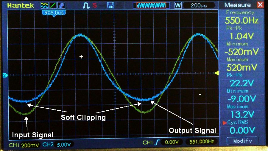
I suggest you plug your guitar in, set all controls as usual, rise volume until you DO get that "ugly distortion" , replace guitar with oscillator, or play an MP3 sinewave, 440Hz is a fine frequency and watch output.
Inject a nice strong signal, say 400 or 500mV, to mimic a high output guitar, rise volume from 0 to whatever�s needed to sound ugly, as soon as it starts becoming ugly look at the screen: what has changed?
Normal is to start with a reasonable sinewave , don�t expect perfection because it�s a gueetar amp, nonlinear by nature, but it should be recognizable.
Typically both (top-bottom) halves will not be mirror images (tube mismatch) and when louder will show some kink (bias shift) ; that is normal in all amps and by itself part of "tube sound"
A few examples of what to expect :
Normal showing some kink. This is NOT crossover distortion, people trying to avoid it overbias tubes to death:


Tube mismatching (or PI not well balanced), to this degree quite normal.
When driven hard one tube stays clean, the other shows lack of stamina. So far no big deal.
Note: these are copypasted images just used as examples, built in comments do not necessarily apply to your problem, if at all.
Similar.
This comes from a stereo Hi Fi tube amp (nothing less than a mighty Mc Intosh 250!!!) : there is not such a thing as perfect matching and even if you get it , in general tubes won�t age the same so after shorter or longer time they will diverge.
To this degree, no big deal, even less on a guitar amp.
Look at these Trainwreck waveforms, going from clean to heavily overdriven, all afre normal:
http://home.polstra.com/amps/wreck1/scope/
Going to do seme useful (as in aid for) work, later will post a gallery of horrors, ugly waveforms.
You might have one of those, or post your own.
It will be most realistic if you use the actual speakers.As this is a Super Reverb the speaker ohms rating is 2ohms. Do I need a 2 ohm load specifically or can I get b wit something different?
Yes, it will get noisy ... but not noisier than actual rehearsing or playing live besides a drummer.
And no need for 2 hour long boring tones, just 1 or 2 minutes will show either normal waveforms or ugly ones.
See above.Next Noob question - what procedure to follow in testing with the scope? Where to probe, what to look for?
In principle, measure at speaker out only, easy 15 V RMS or so.Are there places to avoid with the scope so I don�t damage it?
Why?: if you can hear it, you must see it too.Juan Manuel FaheyComment
-
Yes, but requires adequate heatsinking. Without heatsink the HS50 is specified only at max 14W. So without heatsink 5 HS50/ 10 Ohm in parallel would be good for 70W.A pair of these in parallel is good for a 2.35 ohm load at 100W.Last edited by Helmholtz; 09-30-2019, 05:40 PM.- Own Opinions Only -Comment
-
Yes! Thank you. Probably best to point that out here. Mine are mounted at some distance apart in a 1/8" aluminum chassis with thermal paste. Heat sinking according to the datasheet is vague but seems to imply an aluminum chassis. Nothing fancy or expensive with fins. I expect a good sized aluminum plate, say, 12"x12" at 1/8" or thicker would do. This is still more economical than buying huge, uber high wattage resistors. I'm using the HS50's and I've abused my switchable load box pretty well. It's held up fine.Originally posted by Helmholtz View Post"Take two placebos, works twice as well." Enzo
"Now get off my lawn with your silicooties and boom-chucka speakers and computers masquerading as amplifiers" Justin Thomas
"If you're not interested in opinions and the experience of others, why even start a thread?
You can't just expect consent." HelmholtzComment
-
Originally posted by J M Fahey View Post
15 VRMS
Overload
(2 Ohm/2 x 6L6GC)
For FSR/ 50W/ 2 OhmLoad
OhmPower
W2112.5456.25828.12
Speaker voltage 10 V RMS
For FSR/ 70W/ 2 Ohm
Speaker voltage 11.8 V RMSIt's All Over NowComment
-
What is the chance that one of the four speakers no longer works?
That would be a game changer.Comment
-
Only then would the user find out what is ugly sound.It's All Over NowComment
Comment