Announcement

Collapse
No announcement yet.

Ampeg B15N - FULL restore / blowing fuses

Collapse
X
 
  • Filter
  • Time
  • Show
Clear All
new posts

  • Ampeg B15N - FULL restore / blowing fuses

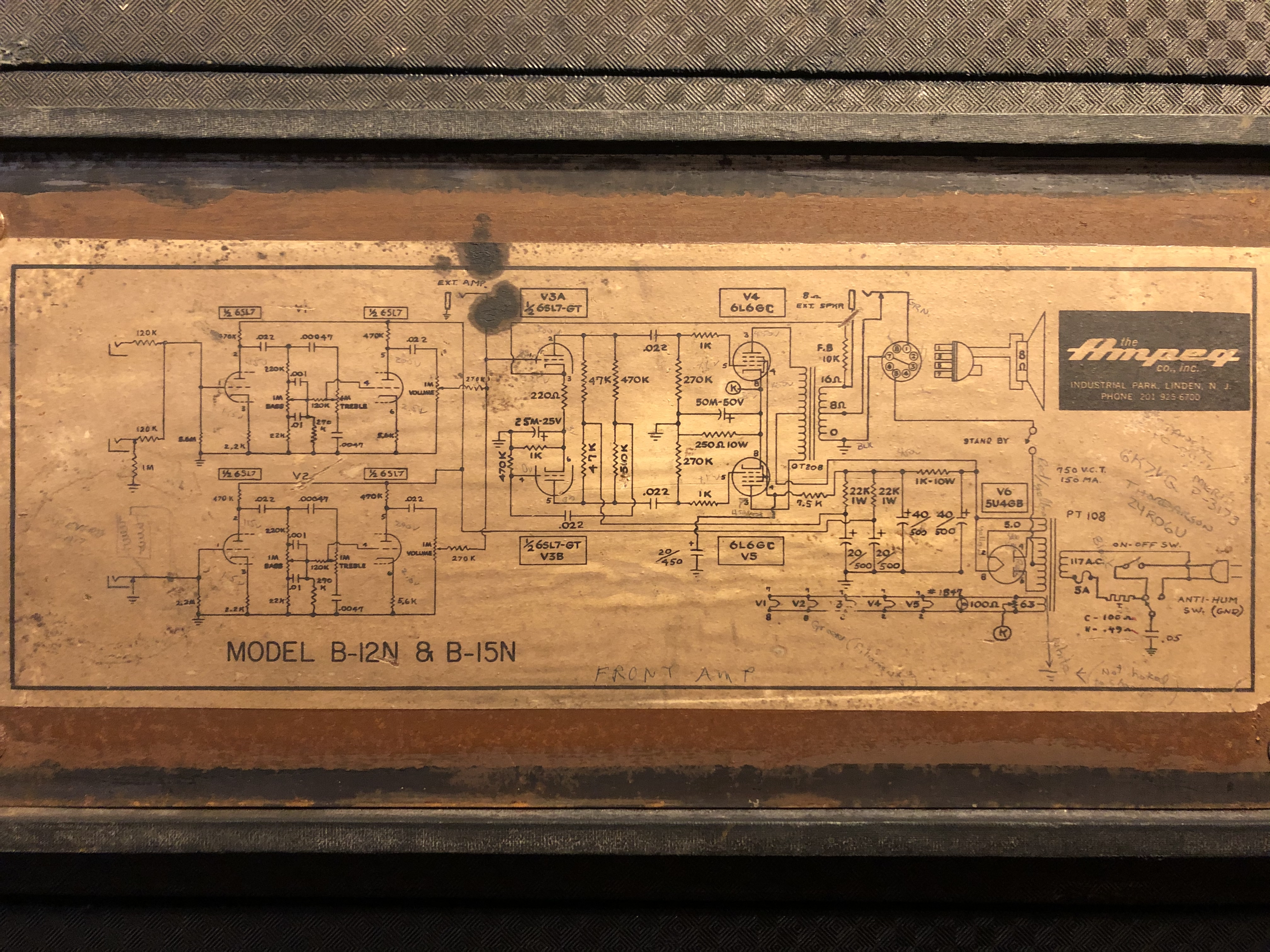
    Another challenge! This is my another oldie that I brought from the attic today and want to bring it back to the playing condition. Still learning those amps, constructions, schematics! It's an early 1963 model, cathode biased. Cabinet has factory upgrade Altec. it has 5U4 rectifier instead of later 5AR4.

    Its blowing fuses just after powered.

    1. I have ordered some caps (40+40+40+40), new power tubes (actual ones have 50-60% emission). Preamp tubes are OK and I already have NOS 5U4GB Sylvania.
    2. I have cleaned some mess inside, cut the 0.5uf death cap and all the connections to polarity switch (it would be there only for cosmetical reasons)
    3. I have cut 2-prong power cut to fit later new grounded one, I will make solid ground in the transformer base
    4. I have cut the original octal "tube" speaker cable (was just dissolving in hands...) also I changed the jack input in the cabinet leaving original housing.
    5. I have cut some strange 2x 50ohm resistors that were wired with two sets of diodes to the pin6 and pin8 of the recitfier (???) I have read something about it, but want to leave it like in the factory (photo)

    Now, I have some questions.

    1. I want to add spekaer input jack on the back of the chassis using the existing hole from the original speaker cable. And here are the questions. Should I make it with washers from both sides like the EXT. SPKR jack that is nearby? (I did that as you seen on the pic but want to make sure). I also have inside 3 wires cut from old speaker cable, RED, WHITE and BLACK (pictured), so I assume I connect black to ground of the new main output jack, then jumper (+) to the (+) of the nearby EXT SPKR jack, right? That leaves the red and white unused - were they for the standby switch "protection" and can be just desoldered all the way? Do I need to put another black grounding to the jack somewhere (saw some shots like that - two black wires coming from the (-) of the main jack spkr out.

    2. Why one of the power cables that run from the on/off switch goes throught 100ohm resistor? (first one from the side of the chassis, black "circle" type) What should be the proper connection without death cap and with the fuse holde (polarity switch completely off)?

    3. Still wondering what is the cause of blowing fuses. Maybe I should check transformers? What is the procedure? I have never done that but It would be nice to know something more!


    Thank you!
    Click image for larger version

Name:	Zdj?cie 15.12.2019, 13 59 59.jpg
Views:	1
Size:	6.90 MB
ID:	876187
    Click image for larger version

Name:	Zdj?cie 15.12.2019, 12 59 49.jpg
Views:	1
Size:	4.68 MB
ID:	876188
    Click image for larger version

Name:	Zdj?cie 15.12.2019, 12 59 17.jpg
Views:	1
Size:	6.24 MB
ID:	876189
    Click image for larger version

Name:	Zrzut ekranu 2019-12-15 o 14.30.58.png
Views:	1
Size:	2.10 MB
ID:	876190
    Last edited by boroman; 12-15-2019, 06:08 PM.

  • #2
    Its blowing fuses just after powered.
    Even without tubes?

    Do you have a bulb limiter?
    - Own Opinions Only -

    Comment


    • #3
      The diodes and resistors wired to the rectifier socket were someones effort to replace the rectifier tube with solid state rectifiers like Fender uses. The resistors are there to add some "sag" to the voltage so it behaves more like a tube rectifier. If you were to buy one of those solid state rectifiers you can plug right into a 5U4 socket, that is essentially what you would find inside it.

      Still wondering what is the cause of blowing tubes.
      What blowing tubes? You said preamp tubes are OK, and the power tubes are simply weak from wear. Is there something I missed? Power tubes wear out, like guitar strings wear out. And ANY tube can fail at ANY time. Yes even new ones. So far no evidence to suggest the most reliable part on the amp - the transformers - have failed.

      Why one of the power cables that run from the on/off switch goes throught 100ohm resistor? (first one from the side of the chassis, black "circle" type
      The black disc is on your schematic in the AC mains circuit, it is labelled T. for thermistor. It is a special resistor that starts cold at a somewhat higher resistance, then over a few seconds warms up and drops to low resistance. This acts as an inrush limiter, and is used by many brands. The schematic calls for 100 ohms or 49 ohms depending on whatever C and V (?) stand for. Yours measures 100 ohms? SOunds like it is right.

      If it were me, I would wire the thing up like the schematic and make it work, and THEN go in and make any changes you may want.
      Education is what you're left with after you have forgotten what you have learned.

      Comment


      • #4
        Originally posted by Helmholtz View Post
        Even without tubes?

        Do you have a bulb limiter?
        Yes, without tubes too.
        Bulb limiter? I often use bulb to discharge caps, but didn't head of bulb limiter term, can you tell me more?

        The diodes and resistors wired to the rectifier socket were someones effort to replace the rectifier tube with solid state rectifiers like Fender uses. The resistors are there to add some "sag" to the voltage so it behaves more like a tube rectifier. If you were to buy one of those solid state rectifiers you can plug right into a 5U4 socket, that is essentially what you would find inside it.
        Understood! OK.

        What blowing tubes? You said preamp tubes are OK, and the power tubes are simply weak from wear. Is there something I missed? Power tubes wear out, like guitar strings wear out. And ANY tube can fail at ANY time. Yes even new ones. So far no evidence to suggest the most reliable part on the amp - the transformers - have failed.
        Sorry, I meant blowing fuses (edited now). Any way to test transformers? I think mess made inside with those resistors, caps measuring strange values (espeically multi-cap) may be the thing too

        The black disc is on your schematic in the AC mains circuit, it is labelled T. for thermistor. It is a special resistor that starts cold at a somewhat higher resistance, then over a few seconds warms up and drops to low resistance. This acts as an inrush limiter, and is used by many brands. The schematic calls for 100 ohms or 49 ohms depending on whatever C and V (?) stand for. Yours measures 100 ohms? SOunds like it is right. If it were me, I would wire the thing up like the schematic and make it work, and THEN go in and make any changes you may want.
        Thanks for the explanation. This is the first B15N that have this resistor from all that I have here! I haven't heard of that thing earlier. I try to read schematic but I'm more kind of visual guy, like red goes here, black goes there etc. Plus those schematic are always not 100% right..

        Comment


        • #5
          Boroman....

          Using this thread, I built a Light Bulb Current Limiter Build Thread.

          You can also watch this video for a further explanation - https://www.youtube.com/watch?v=wRFRwOnLsZI
          Attached Files
          It's not just an amp, it's an adventure!

          Comment


          • #6
            Amgeg B15N Schematic

            The first thing I would do is to remove all the tubes, make sure there are no hanging wires in the amp (looks like you removed the diodes and resistor acting as the rectifier), plug the amp into the Bulb Limiter, and then turn the amp on.

            Does the Bulb Limiter lamp glow brightly? If yes, you have a problem.
            Does the lamp barely glow? A better sign.
            Does your amp's power indicator lamp glow? A good sign.
            Do you measure 6.3v across the Green & Green/Yellow wires? If yes, a good sign.
            Do you measure 5.0v across the Yellow & Yellow/White wires? If yes, a good sign.
            What about each of the Red to Red/Yellow leads?

            This would be a good indication if your Power Transformer is ok. From there, you can continue to work forward.

            BE CAREFUL !!
            It's not just an amp, it's an adventure!

            Comment


            • #7
              Do you measure 6.3v across the Green & Green/Yellow wires? If yes, a good sign.
              Will be lower with the bulb limiter. PT voltage verification does not work on the bulb limiter.
              - Own Opinions Only -

              Comment


              • #8
                Thank you Helmholtz...

                In my hurry, I should have stated that if steps 1, 2, and 3 and good, disconnect the limiter then take the voltage measurements. Good catch!!

                Tom
                It's not just an amp, it's an adventure!

                Comment


                • #9
                  I took it to the tech today (who had bulb limiter!). It looks that PT is toasted.... unfortunately. I will make sure for 100% when I desolder it completely. We haven't tested OT much, but from the basic tests it's probably okay.

                  Comment


                  • #10
                    If PT is indeed damaged with these Flip tops, it is much better to get them rewound and re-potted. I have done two with a company in Orono, Maine, TRS, Transformer Rewinding Service.
                    It's weird, because it WAS working fine.....

                    Comment


                    • #11
                      Originally posted by Randall View Post
                      If PT is indeed damaged with these Flip tops, it is much better to get them rewound and re-potted. I have done two with a company in Orono, Maine, TRS, Transformer Rewinding Service.
                      But then, somewhere closer to Poland might be more convenient
                      "Take two placebos, works twice as well." Enzo

                      "Now get off my lawn with your silicooties and boom-chucka speakers and computers masquerading as amplifiers" Justin Thomas

                      "If you're not interested in opinions and the experience of others, why even start a thread?
                      You can't just expect consent." Helmholtz

                      Comment

                      Working...
                      X