Announcement

Collapse
No announcement yet.

Kustom K100C-8 repair

Collapse
X
 
  • Filter
  • Time
  • Show
Clear All
new posts

  • Kustom K100C-8 repair

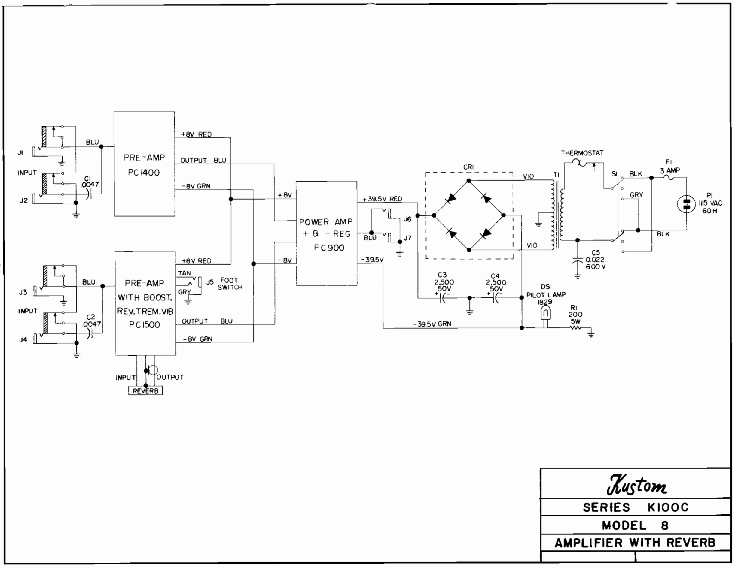
    I have a Kustom K100C-8 on the bench. Schematics attached. All functions work, but sound is poor--right channel (simple one) is almost OK, but distorts unpleasantly when hit with a hard guitar chord; left channel is very low in volume and distorted.

    Rail voltages test OK, if a little unbalanced (and my line voltage is reading 115vAC just now, a rare thing in my 'hood, usually 120-122): HV rails are 38.5 and -37.9vDC, and LV rails are 8.26 and -7.93vDC.

    I will certainly check diodes, resistor values, etc, so I have work to do. But my first question is about replacing the two main filter caps (2200u/50v)--any problem replacing them with the 10,000uF/50v caps I have on hand? (I know to respect tube rectifier limits, but here, we're dealing with solid state.)


    Click image for larger version

Name:	Kustom K100C block.png
Views:	1
Size:	397.2 KB
ID:	876202Click image for larger version

Name:	Kustom K100C PC900.png
Views:	1
Size:	2.50 MB
ID:	876203Click image for larger version

Name:	Kustom K100C PC1500.png
Views:	1
Size:	2.21 MB
ID:	876204Click image for larger version

Name:	Kustom K100C PC1400.png
Views:	1
Size:	1.27 MB
ID:	876205
    --
    I build and repair guitar amps
    http://amps.monkeymatic.com

  • #2
    Now I'm tracing signal. I can get about 42 watts clean into a 4ohm resistive load, though I see a minor x-over notch.

    On the left channel, I traced the signal degradation right to the input. I put my probe on the spot shown by the red arrow. When amp is OFF, sine wave looks perfect...but as soon as I turn the amp ON, the sine wave drops in voltage, and gets distorted, as shown. How is that possible? Does that suggest C1500 is leaking DC? Or Q1500 is bad? In measuring the DCR of the various legs of the transistor, I get 60-90Kohms.
    --
    I build and repair guitar amps
    http://amps.monkeymatic.com

    Comment


    • #3
      Oops, here's the image:

      Click image for larger version

Name:	kustom1.jpg
Views:	1
Size:	510.5 KB
ID:	856363
      --
      I build and repair guitar amps
      http://amps.monkeymatic.com

      Comment


      • #4
        But my first question is about replacing the two main filter caps (2200u/50v)--any problem replacing them with the 10,000uF/50v caps I have on hand?
        In my mind it is better to FIX it first, then go about updating any parts. 10,000 would probably be OK, but perhaps overkill. I suspect the amp was not overly hummy with the 2200uf stock caps. You have the two 38v supplies, how much ripple is on them? And you have both 8v supplies, and I suspect they are clean too. Your complaint is not hum, it is weak signal or distortion.

        As to symptom, resistance measures of the transistor won't tell us much unless it is shorted. That is what the diode test on your meter is for, check transistors that way.

        Your distortion looks like rectification to me, or at least severe clipping on one side. But first, your schematic has voltages all over it. How close are yours? Q1500: os ther zero DC on the base? Is there about +7.7v on the collector? And about -0.8 (or is that -0.5?) on the emitter?

        C1500 is not so likely LEAKING DC as it might be coupling the signal into a wall of DC on the righthand side.
        Education is what you're left with after you have forgotten what you have learned.

        Comment


        • #5
          Thank you, Enzo. Here are my measurements for the first two transistors. Expected values, according to the schematic, are shown in (parens):

          Code:
          Q1500              Q1501
          C ( 7.7)  7.2      E ( 7.5)  7.8
          B ( 0.0) -0.6      B ( 7.7)  7.2
          E (-0.5) -1.2      C (-1.0) -1.5
          Is that enough of DC shift to screw up the first stage?
          --
          I build and repair guitar amps
          http://amps.monkeymatic.com

          Comment


          • #6
            Want to hear a funny story? I noticed that someone had replaced Q1500, the first gain stage, with a modern NPN...all the other transistors are original. So I had a close look, and saw that the NPN was in BACKWARDS! I flipped it around and the channel works!

            This amp was sold by [a big box guitar store] as "very good" condition. Yeah, right.

            Merry Christmas!
            --
            I build and repair guitar amps
            http://amps.monkeymatic.com

            Comment


            • #7
              The datasheet that I found shows the pin assignment as EBC.
              So the emitter and collector leads where in the wrong configuration.
              Nice Christmas present getting the problem solved!

              Comment

              Working...
              X