Announcement
Collapse
No announcement yet.
Magnatone Custom M10
Collapse
X
-
Originally posted by The Dude View Post...build a cap coupled negative supply off the HV winding if you want to save the cost of a new transformer.
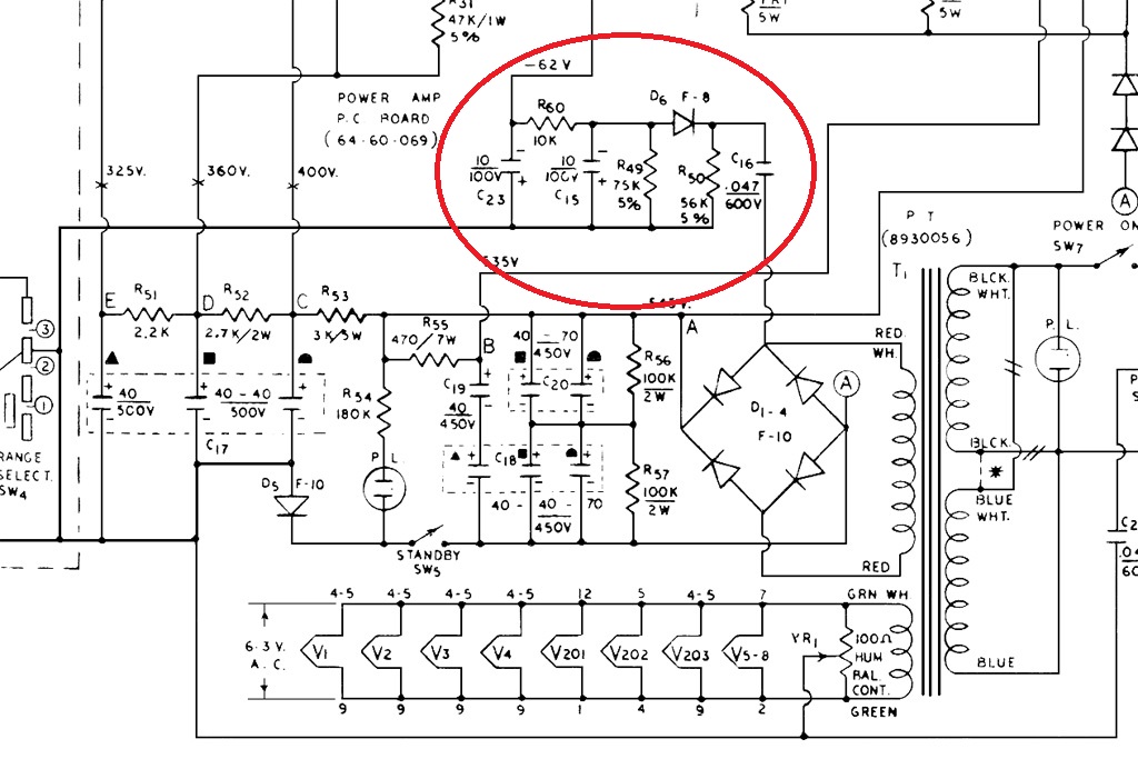
Edit: Attaching the relevant section of an Ampeg V4. You'd need to adjust values for your particular application.
[ATTACH=CONFIG]56935[/ATTACH]
where is the "?" connected to, ground?
thx!
PS: those +400VDC will be achieved after going through the 40uF/450V cap (the value is there to represent the HV DC)Last edited by TelRay; 02-11-2020, 11:59 PM.
Comment
-
Yes. The "?" is ground.
Yes. You can use 1N4007. Notice polarity for negative voltage.
Cap values should be fine, although I might use higher values to provide more filtering for the BJT stage.
You should need only to make resistor changes to R49 and R60.
Also, you can simply pull the output tubes until you get voltages correct.Last edited by The Dude; 02-12-2020, 01:04 AM."I took a photo of my ohm meter... It didn't help." Enzo 8/20/22
Comment
-
Some good info contained here: http://www.valvewizard.co.uk/bias.html
Might get a little tricky to get -50V from standard circuit values and lowish 400V HT. But with some resistor value adjustments to the amp -40V should suffice.- Own Opinions Only -
Comment
-
58 mA seems too little. This one https://www.hammfg.com/files/parts/pdf/370DX.pdf at 104 mA with the same voltages would be better, although maybe still a bit on the light side. 370EX might be a better choice at 144 mA https://www.hammfg.com/files/parts/pdf/370EX.pdf
18 watt Marshall replacement from Hammond is rated at 140 mA as a point of reference.
Comment
-
this ^^^^^^
I built an amp from scratch, 2x 6V6, with a 100ma PT. I learned the hard way that I needed more. Go with the 370EX if you're thinking about 2x 6V6 or equiv.If it still won't get loud enough, it's probably broken. - Steve Conner
If the thing works, stop fixing it. - Enzo
We need more chaos in music, in art... I'm here to make it. - Justin Thomas
MANY things in human experience can be easily differentiated, yet *impossible* to express as a measurement. - Juan Fahey
Comment
-
thank you guys!
FYI the PT we were trying to get to work (369BX) delivers 86 mA so I guess this just confirms that even if we got it to provide 400 VDC and -50 VDC it would have felt short on the current side, right?
I am looking for Hammond because that's the one that came with amp and I know they have some good reputation. I am open to other manufacturers if you have a recommendation.
Best,
Comment
-
hello y'all, news from the front...
- had the new power supply installed (after doing some mechanical engineering)
- put the rectifier back to full wave
- removed the 2x death capacitors from ANTI-HUM 1 and 2 (as the amp already has now a 3 prong mains connector properly grounded)
- VOLTAGES as expected:
* HV +395 VDC [NOMINAL 400 V]
* BIAS -67 VDC [NOMINAL -50 V]
- CURRENT DRAW (reading at variable isolation transformer): 0.4 A
So... the amp is alive!
There's not much indication of reference voltages in the schematics (and some of them are impossible to read), so I have measured the following ones:
QUESTION #1: How can I achieve the required BIAS VOLTAGE?
QUESTION #2: (for my understanding) what's the "damage" i am inflicting by running the amp at a 35% lower (or higher) BIAS VOLTAGE? Killing the power tubes life span? running them to cold? how safe is to keep testing the amp like this?
At a certain point I connected the REVERB TANK and the overall sound (both WET and DRY) got distorted.
I played like that for a while (5-10 minutes) until I've heard a loud "pop" coming from a blown capacitor (connected to PINs 1 and 6) on the 12AU7 tube driving the reverb.
The blown capacitor was new and one of the electrolytics i have replaced. What I do not remember is if the original capacitor was polarized or not. On the schematic there's no indication of polarity, though. I would usually not replace a cap if i am not certain about polarity (but this was done a few weeks ago, so i don't remember).
In any case, this is the polarity I have used:
I have researched the Schematics for the Magnatone M10"A" and it shows a polarized cap with the opposite polarity I have used :/
QUESTION #3: did I get the polarity wrong (is it not clear in the schematic)?Last edited by TelRay; 02-20-2020, 07:24 PM.
Comment
-
Yes, wrong polarity. Positive must go to the plates. (In case of doubt just varify voltage polarity with your meter with bad cap removed before connecting a new cap.)
Bias voltage can be adjusted by lowering the 12k resistor to 8.2k. Increasing the value of 120k resistor will drop the BJT supply.Last edited by Helmholtz; 02-20-2020, 07:18 PM.- Own Opinions Only -
Comment
-
hello guys,
mission successful! after playing with resistor values for a while I got the right VOLTAGES for the BIAS and the REVERB. Also put back the old (1uF 450V) CAPACITOR on the reverb tube and everything works
now that all VOLTAGES are within spec I need to test this baby extensively to find all the other nuances I need to fix... but you knew that was coming
thank you!!!
PS1: I needed to go much higher than I expected in the resistor value for the BJT supply (120K to 450K)
PS2: I do not remember who told me not to expect a dirty sound out of this amp... but at full volume it overdrives very graciouslyLast edited by TelRay; 02-21-2020, 07:09 PM.
Comment
Comment