Announcement

Collapse
No announcement yet.

Still in need of cooler 6L6's....advice please

Collapse
X
 
  • Filter
  • Time
  • Show
Clear All
new posts

  • Still in need of cooler 6L6's....advice please

    I'm still working on a MIJ bass amp from the 60's.... yes I know it's been 2 weeks ( on and off though ). There is a 4ohm tap off the OT that is not being used. The wire is dangling inside the chassis. Currently the 8ohm tap is connected to the speaker jack and functional. I was wondering if disconnect the 8ohm tap and swap it with the 4ohm tap and run a 4ohm speaker would this cool my output tubes or vice-versa or no change?

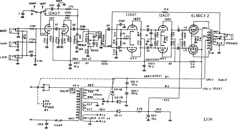
    Lafayette Bass Head (Univox 1236).

    My main concern right now is, "slight" orange plating on the two 6L6's when tested. At idle (line voltage at 116V) the plates are reading 660V. I've been through the amp lifting and replacing components that are off spec by 20% or more. My line voltage on the bench is 123V and the schematic measurements were performed at 117V. I know this will bump the 6L6 plate voltages up about 40V+. I tried to adjust the bias at idle to make them cooler, but I've pegged the pot, no room left. Does biasing them hotter at idle make them run cooler when they are pushed (thought I read that someplace)?

    I wouldn't usually be "as concerned" with an old amp made in Japan, figuring, it is, what it is and leave well enough alone but.... the amp has a very unique sound which is actually quite pleasant and worthy of using on smaller gigs.

    I'm not savvy enough at this point to alter the circuitry enough to cool things down for modern day usage. Soooo.... I would most appreciate any knowledge given forward, from the guru's within this forum. Many thanks, once again.

    Regards,

    Gary


  • #2
    Changing the speaker load and tap wont change your red plating. You need to increase your bias voltage potential ( for example... -32 volts to -42 volts). According to your schematic the two cathodes of the output tubes share a 10 ohm resistor to ground. For a 660 volt supply each tube should be idling around 20 ma. Adjust your bias till you read about 400 milli volts across the 10 ohm resistor. If the tubes are matched that should be around 20 milli amps per tube. If you can't adjust your bias higher then increase the resistor values in the bias supply (33K to 47K). Hopefully that will do the trick. Remember this is just my advice. I'm sure someone will probably disagree with me. Be careful and good luck.

    Comment


    • #3
      Thanks Twist for the advice. Would changing the 10ohm cathode resistor value be another way? The reason why I ask is, when I got the amp in for repair, someone had previously removed the original 10ohm 2w resistor and replaced it with 2 10ohm 2W sand resistors in parallel to yield 5ohms. I removed that mod and went back to what the schemo called for. I hadn't taken any readings with that config.

      Comment


      • #4
        I would leave the 10 ohm in there and work on the bias voltage levels.
        Try a 50KL pot in place of the 33K resistor (in the bias supply) and instead of grounding one leg of the pot, lift it off ground with a 15K resistor. It might not be a bad idea to also replace the 10uf 50 volt cap with a 100uf 100 volt cap.

        Comment


        • #5
          nice idea... I already changed the 10/50 to a 10/150, actually, I replaced every cap on the board.

          Thanks again!!

          Comment


          • #6
            At 660vp your going to cook those tubes pretty fast, even if you bias them cool. In fact it sometimes happens that the cooler you bias them, the higher the vp will go, making things even worse.

            Are you sure the amp is designed to run 6L6s? Where did that schematic come from?

            Doesn't matter. I'd change to 6550s or el34s at least.

            Chuck
            "Take two placebos, works twice as well." Enzo

            "Now get off my lawn with your silicooties and boom-chucka speakers and computers masquerading as amplifiers" Justin Thomas

            "If you're not interested in opinions and the experience of others, why even start a thread?
            You can't just expect consent." Helmholtz

            Comment


            • #7
              Maybe use the pink tap on the PT secondary instead of the red? Unless it's voltage is a significant amount lower, it might get you back in the ballpark for B+. Man, with 660v and a 10k primary on the OT, the voltage swings on the plates of the 6l6's must be pretty radical when it's really cooking...
              Sometimes I'm good, then I'm bad..
              http://www.evacuatedelectronics.com

              Comment


              • #8
                Originally posted by Chuck H View Post
                At 660vp your going to cook those tubes pretty fast, even if you bias them cool. In fact it sometimes happens that the cooler you bias them, the higher the vp will go, making things even worse.

                Are you sure the amp is designed to run 6L6s? Where did that schematic come from?

                Doesn't matter. I'd change to 6550s or el34s at least.

                Chuck
                Well I wouldn't panic yet... the 6L6's screen voltage is half the plate voltage in that one.
                I have found that those old Univox chassis amps used some inferior coupling caps and many times they would be leaking DC to the grids of the next stage... sometimes that would mean the power tube grids.
                If you have those odd shaped, pukey greenish colored caps, I'd just replace them all with any generic plastic cap like a Mallory 150s, Xicon MPPs or even WeberVST caps.
                Regardless, I would rebuild the bias supply so I had at least -45vdc to -55vdc available.
                Mess around with the bias supply voltage divider.
                Remove that 6k2 and 33K resistor.
                Try something smaller for the 6K2, like 1k5 or 2k7
                Sub that 33K for a 25K trim pot in series with a 15K to 20K 1/2 resistor.
                Drop the small value 10uF filter cap and use at least a 100v, 47uF to 100uF cap instead.
                **************

                Sorry.. I see you've already done most of that.
                Last edited by Bruce / Mission Amps; 01-03-2008, 09:19 PM. Reason: Oops reread the thread
                Bruce

                Mission Amps
                Denver, CO. 80022
                www.missionamps.com
                303-955-2412

                Comment


                • #9
                  Thanks everyone!

                  To answer a few questions.

                  6L6 is stamped on the chassis.
                  Radical?..... well, only played it for a few minutes to see where the voltage was going to end up.
                  All the coupling caps were replaced with 150's.

                  I'm liking the idea to first get the bias supply rebuilt so I have some room.

                  thanks again!!

                  Comment


                  • #10
                    What is the actual bias voltage AT THE SOCKETS? Is it the same as at the supply?
                    Education is what you're left with after you have forgotten what you have learned.

                    Comment


                    • #11
                      O.K. perhaps you still need to get the bias voltage dialed in. So when that's figured out...

                      What could possibly be the harm in NOT running 6L6s at 660Vp. I've never tried it. Maybe it can be done, and I'm always up for an education. But even with the screens low, isn't that about 200 volts too many on the plates? Maybe the amp can be made to work ultimately. But I wonder if it can ever be ideal with that kind of scenario. I'd change to 6550s anyway.

                      Chuck
                      "Take two placebos, works twice as well." Enzo

                      "Now get off my lawn with your silicooties and boom-chucka speakers and computers masquerading as amplifiers" Justin Thomas

                      "If you're not interested in opinions and the experience of others, why even start a thread?
                      You can't just expect consent." Helmholtz

                      Comment


                      • #12
                        They arc or they don't. Does that model or series have a history of blowing up a lot?

                        If Leo Fender can run little 6V6s 100 volts over specs, well...
                        Education is what you're left with after you have forgotten what you have learned.

                        Comment


                        • #13


                          Here are my readings. Thanks everyone.

                          6L6

                          pin 3 652V
                          pin 4 329V
                          Pin 5 -25.4

                          -36.2 coming out of the diode SD-1Y and -32.5 on the other side of the resistor following it. (see notes below about this resistor).

                          there is no arcing evident on the sockets.

                          This amp has been dormant for 17 years so any past history is unknown. I've researched the type and model and not a mention of performance or faults could be found.

                          the schematic I have is for a Univox not a Lafayette. Research has told me that this is the closest schematic available as the two companies were virtually the same (sorry if I slightly off on this). The schematic I have runs on the money with how this amp is designed with one exception, which I found out last night. The resistors in the bias section are not the same. Where you see a 6.2k resistor on the schem, the actual resistor on this amp is a 3.3K. the other 33k resistor is actually a 26K resistor (I checked it 3 times) attached to one leg of the trim pot and to ground. The violet leads from the transformer to the bias section, as shown in the schem above are not violet in this amp nor can I find -50V on the transformer side of the SD-1Y diode, also shown on the schem above. Those are the only differences.
                          Last edited by Garydean; 01-04-2008, 04:30 PM.

                          Comment


                          • #14
                            First off, Lafayette was a huge electronics retailer on the East coast back in the 60-70's, not unlike what Allied Radio once was. They had any number of companies build and house brand amps and guitars with the Lafayette label. This amp was probably built for them by Unicord and that's why the circuits are nearly the same.

                            "The resistors in the bias section are not the same. Where you see a 6.2k resistor on the schem, the actual resistor on this amp is a 3.3K. the other 33k resistor is actually a 26K resistor (I checked it 3 times) attached to one leg of the trim pot and to ground."
                            The resistor values that your amp has, would allow for a higher bias voltage than shown in the schematic, as long as the input from the transformer was the same. Is the trim pot wired in series to ground with the 25K resistor? If so, when you adjust the trim pot how high can you get the voltage at pin 5 of the output tubes? -33 volts? Is that enough to get the current draw down to a reasonable level?

                            "The violet leads from the transformer to the bias section, as shown in the schem above are not violet in this amp nor can I find -50V on the transformer side of the SD-1Y diode, also shown on the schem above."
                            You'll never see -50 volts coming out of any transformer, transformers are AC devices that's just a misprint.

                            If you can't get enough bias voltage out of the circuit, you could wire up a voltage doubler to increase the bias voltage.

                            Comment


                            • #15
                              thanks Bill!!

                              "Is the trim pot wired in series to ground with the 25K resistor? If so, when you adjust the trim pot how high can you get the voltage at pin 5 of the output tubes? -33 volts? Is that enough to get the current draw down to a reasonable level?"

                              yes it is wired in series. I never checked the max -volts I was able to get. When I dialed counter clockwise the plate voltages would rise close to 700 so I backed off. I was able to get -33volts with the trim pot half way
                              Last edited by Garydean; 01-04-2008, 11:04 PM.

                              Comment

                              Working...
                              X