Announcement

Collapse
No announcement yet.

some hum in my new 5e3

Collapse
X
 
  • Filter
  • Time
  • Show
Clear All
new posts

  • some hum in my new 5e3

    Hi!

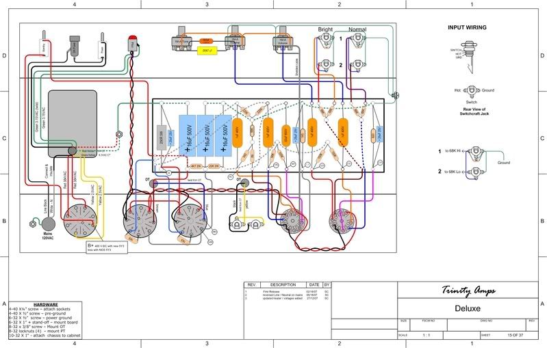
    I'm new to bulding amps, and i've just completed my first one, a Fender 5e3!
    Everything seems fine, i like the tone, but theres some hum. No that much, so that there's a major problem somewhere, but i'm sure that its above normal.
    Turning the vol pot amplifies the hum and
    there's a hiss increasing when turning up the tone pot. Turning the guitar pot up or down doesnt seem to have an affect.

    I've about 347V at my first filter cap. Measured around 6.5 at the filaments and pilot light. These voltages seems almost steady (+- 0,01-0,02V )
    What strange is, that sometimes the pilot light gets brighter or darker for a while few moments.

    I made 1 connection to the chassis near the PT, and gatherered all the grounds there (PT, jacks (isolated), filter caps, pots, safety ground, everything is directly connected with a separate wire to this point, no local star grounds, buses..). Is this okay?

    Poking around with a chopstick didnt help. I've changed the rectifier tube too.

    I'm sure i did something wrong, but what is that?

    bye,
    Rody

  • #2
    sounds like your grounding scheme is wrong and is probably a source of the hum problem.

    Comment


    • #3
      Try moving the preamp grounds, pot grounds & screen supply filter cap ground to another ground point, prefereably at the Normal/Mic #1 input jack?

      Pilot light could be the bulb or intermittent connection in the fuse holder, try a new bulb first.

      Comment


      • #4
        I had grounding trouble too. Asked on another forum and got this.
        Chopped out my 'best guess' grounds and followed it.
        Perfect.


        Hmm, that showed up a little small -- there's some intricate detail at the inputs.
        There's a larger image of it in this thread
        http://www.guitarscanada.com/Board/s...ad.php?t=11412

        Comment


        • #5
          Originally posted by rody82 View Post
          Hi!


          I made 1 connection to the chassis near the PT, and gatherered all the grounds there (PT, jacks (isolated), filter caps, pots, safety ground, everything is directly connected with a separate wire to this point, no local star grounds, buses..). Is this okay?


          bye,
          Rody
          I've read that it's a good idea to keep the earth ground away from the signal ground for noise reasons.
          Sine Guitars
          Low-Impedance Pickups

          http://sineguitars.webs.com

          Comment


          • #6
            +1 on removing the earth ground from signal ground. Place the signal ground and earth ground about 2" apart. That might help a bit.

            One thing I hate about star grounding is that you have to use crappy plastic jacks unless you use a system of washers to isolate grounds from the chassis. Ideally, you could give a buss grounding scheme a try. Check this out: http://www.el34world.com/charts/grounds.htm. My 5E3 used to use a star ground and it worked OK, but I changed to the buss ground and it worked much better (as in, less hum).
            In the future I invented time travel.

            Comment


            • #7
              Your "high current grounds",the main filter,the cathode resistor on the power tubes,OT ground and your 6.3vac center tap and the ground lug from the AC supply wire should be at or near the PT,all the others should be at the other end of the chassis.

              Comment


              • #8
                Originally posted by stokes View Post
                Your "high current grounds",the main filter,the cathode resistor on the power tubes,OT ground and your 6.3vac center tap and the ground lug from the AC supply wire should be at or near the PT,all the others should be at the other end of the chassis.
                Hi Stokes

                Without wanting to intentionally hi-jack this thread, I have a similar question (if you don't mind me asking you) in relation to the 5G9. Is the PI ground in that circuit a 'high current' or 'low current' ground (and what about the trem ground and the bias supply ground)? Methinks that at least the PI ground and probably the Trem ground the would be a 'low-ish' current ground, but I have seen grounding circuits where the PI ground is kept with the output ground.

                Basically I am wanting to do a split ground, but I don't know whether its best to ground the bias, trem and/or PI with the pre-amp grounds, or with the output cathode/heater/mains ac grounds.

                What's your esteemed opinion then?

                Cheers
                Building a better world (one tube amp at a time)

                "I have never had to invoke a formula to fight oscillation in a guitar amp."- Enzo

                Comment


                • #9
                  I would start by saying I dont know if the terms "high" or "low" current grounds is technically correct,but the bias,trem and PI grounds I would consider low current grounds.I dont use a total star ground scheme,but try to keep the preamp grounds as far away from the previously described high current grounds as possible without getting too carried away with running ground wires the entire legnth of the chassis.Its always worked for me.I know there are some who feel the full star ground is the only way to go,and even isolate the input jacks and ground them elsewhere,which is fine,I've just never had the need.Always found it sufficient just to keep what I described as high current grounds by the PT,if not actually on the PT mounts and all the rest towards the inputs end of the chassis.

                  Comment


                  • #10
                    The mistake usually made is to tie all the filter cap grounds to the same place. The preamp filter's ground should go to the chassis ground near the input jacks.

                    A safety note on the layout posted by dobsont. See how the hot side of the line goes to the side terminal on the fuse holder. This is bad because it allows you to touch one side of the line when you are installing a good fuse. The hot side of the line should go to the back terminal.
                    WARNING! Musical Instrument amplifiers contain lethal voltages and can retain them even when unplugged. Refer service to qualified personnel.
                    REMEMBER: Everybody knows that smokin' ain't allowed in school !

                    Comment


                    • #11
                      Originally posted by dobsont View Post
                      I had grounding trouble too. Asked on another forum and got this.
                      Chopped out my 'best guess' grounds and followed it.
                      Perfect.

                      There's a larger image of it in this thread
                      http://www.guitarscanada.com/Board/s...ad.php?t=11412
                      Thanks dobsont

                      That's what I would call a 'split-ground'. Although I though that the reservoir cap and the screen decoupling cap should be grounded together, and the pre-amp decoupling cap grounded separately (with the other pre-amp grounds). Did you wire your grounds exactly like this diagram?
                      Building a better world (one tube amp at a time)

                      "I have never had to invoke a formula to fight oscillation in a guitar amp."- Enzo

                      Comment


                      • #12
                        Originally posted by loudthud View Post
                        The mistake usually made is to tie all the filter cap grounds to the same place. The preamp filter's ground should go to the chassis ground near the input jacks.

                        A safety note on the layout posted by dobsont. See how the hot side of the line goes to the side terminal on the fuse holder. This is bad because it allows you to touch one side of the line when you are installing a good fuse. The hot side of the line should go to the back terminal.
                        Just to add to this,the screen cap should be grounded with the preamps as well.It would seem otherwise,but this is a common problem with hum in some old Fenders that had the screen cap grounded with the main supply cap.I left something out earlier,the HV CT should be grounded at the PT with the other "high current" grounds.

                        Comment


                        • #13
                          Originally posted by stokes View Post
                          Just to add to this,the screen cap should be grounded with the preamps as well.It would seem otherwise,but this is a common problem with hum in some old Fenders that had the screen cap grounded with the main supply cap.

                          Thanks for that bit of info Stokes. I must try this on my 5F2A - at present I have the screen ground wired with the reservoir cap
                          Last edited by tubeswell; 05-02-2008, 12:52 PM.
                          Building a better world (one tube amp at a time)

                          "I have never had to invoke a formula to fight oscillation in a guitar amp."- Enzo

                          Comment


                          • #14
                            Originally posted by tubeswell View Post
                            Thanks for that bit of info Stokes. I must try this on my 5F2A - at present I have the screen ground wired with the reservoir cap
                            Please do, I'd like to know if that really makes any difference what so ever.
                            Bruce

                            Mission Amps
                            Denver, CO. 80022
                            www.missionamps.com
                            303-955-2412

                            Comment


                            • #15
                              Originally posted by tubeswell View Post
                              Hi Stokes

                              Without wanting to intentionally hi-jack this thread, I have a similar question (if you don't mind me asking you) in relation to the 5G9. Is the PI ground in that circuit a 'high current' or 'low current' ground (and what about the trem ground and the bias supply ground)? Methinks that at least the PI ground and probably the Trem ground the would be a 'low-ish' current ground, but I have seen grounding circuits where the PI ground is kept with the output ground.

                              Basically I am wanting to do a split ground, but I don't know whether its best to ground the bias, trem and/or PI with the pre-amp grounds, or with the output cathode/heater/mains ac grounds.

                              What's your esteemed opinion then?

                              Cheers
                              on the schematics that give detailed voltages, you can just calculate the current(since you can obtain V and R; V/R=I). For the PI probably about 1mA per triode. The (current) levels you see in an amp would be something like uA(microamp= one millionth of an amp) range for pickup and grids(across grid--not through), single mA (one thousandth) for triodes, tens of mA(static and higher when drawing signal for output tubes), around 100-something mA for a B+ winding(max.--depends what the load is--example, say 40mA x 4 output tubes plus couple mA for pres = around 163mA), Amps for heaters, spk. out(at max. signal=max.current). Basically you're supposed to try to do what that Henry Ott guy said (try to make youself concious of what is happening in the ground line)--and you can see an extension/application to tubes in the Kimura article.

                              Comment

                              Working...
                              X