 Tweet
Tweet
This is an old PA amp converted to a guitar amp some years back, not by me.
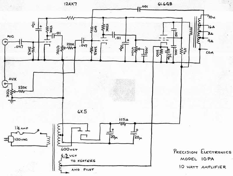
I made a few notes and took several pictures so installing the new 80/30/40/20 x 525v multicap would be easier. I pulled out the 40/20/20/10 x 400/400/350/350 this morning. The old can had the triangle, square, D, -symbols stamped in such a way where they could only be seen after removing the can. OK so what... according to the schem below the cathode capacitor of the output tube should be a 25uF right? Well it was connected to the 10mf/350v lug of the can. The 40/400v section was filtering the B+ off the rect, the 20/400v was also filtering B+, the 20/350v was connected to the screen grid of the 6L6.
Any suggestions on connecting the new can? What part of the circuit should have the greatest capacitance and would benefit from the 80/525v section? Would all the other values work well no matter how it's installed?
the coupling cap off the 12ax7 is shown on the schem below and had been replaced with a 20/450v a few years ago.
Thanks for you advice,
Gary
Comment