 Tweet
Tweet
Originally posted by Tonefishin
View Post
-
Just a guess but I think you might be tripping over that concept. The pot is not used as a variable resistor but as a variable voltage divider. If you want model of a 1meg pot turned all the way up, change R2 to 1M and connect it as mooreamps says. If you want to model the pot at halfway, leave R2 as is and connect another 500k resistor from the bottom of it to ground. -
Tripping...I'm totally stumbling...but still trying.Originally posted by Ptron View Post
I tried both ways but it didn't change things much on the output of that first triode...hmmmm! I've checked out the tube model and very closely duplicazted the tube curves, so I'm pretty sure that is ok...
Comment
-
Moving from R2 alone to R2 and R4 is not going to have much effect on the signal at the first triode, after all they are after it, but it will affect what goes on to the grid of the second triode. The output of the second triode - the signal at its plate - should change dramatically between the two arrangements.Education is what you're left with after you have forgotten what you have learned.Comment
-
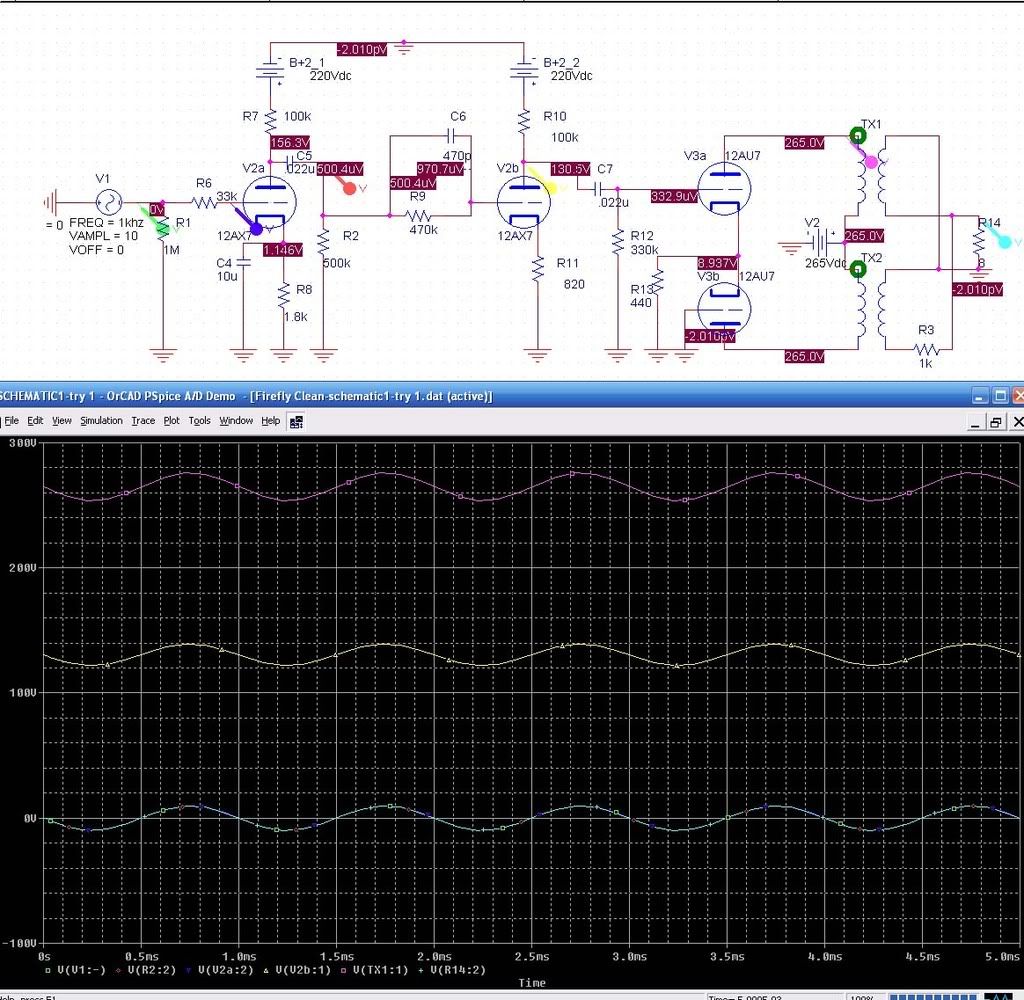
So what's the problem? I can't see one, other than that your push-pull output transformer has a 1k resistor in there for some reason. The voltages that PSpice displays on the schematic are DC voltages from the initial DC bias point analysis. They're not RMS signal voltages from your transient analysis. Having said that, the waveforms look weird: everything seems to have a gain of 1. (You're overdriving the first tube massively, FWIW: try an amplitude of 0.1V instead of 10)
I'm also not convinced by the whole concept of designing tube amps with PSpice. I think it makes it look more involved and complicated than it really is to just slap some tubes together and get them making noise. As it is, you're having to learn all about tubes at the same time as you learn about circuit analysis with Spice, which I never really "got" until I was taught how to use it as an EE student. (For instance, did you know about the differences between the three types of analysis Spice offers: DC, AC, and transient?)
PS: You can make a real three-winding transformer by placing three inductors and a "K" object to couple them. I think. It's been a long time since I used Orcad.
Oh, and remember that in PSpice, "1M" means the same as "1m": one thousandth of an ohm. If you want one megohm, use 1000k.Last edited by Steve Conner; 07-16-2008, 11:08 AM."Enzo, I see that you replied parasitic oscillations. Is that a hypothesis? Or is that your amazing metal band I should check out?"Comment
-
pSPice may have suggested a series resistance for the output transformer, but 1k is WAY too high a value! You should try something like 0.25-1.0 Ohms in series.
Remember, the transformer is driveing a 4-8 Ohm speaker. If you put 1000 Ohms in series with the speaker you just end up with a huge voltage divider. You are essentially not using one half of the transformer. A very small resistor willbe more in scale with the rest of the impedance i the transforemr secondary and will likely satisfy pSPICE just as well as the 1k.
ChrisComment
-
Thanks. I don't understand why the difference in the V2b plate output is not reflected between the two runs...hmmm.Originally posted by Enzo View PostComment
-
Ok. I only changed to 10V to verify I was getting the sine generator. You're right, it would over-drive that tube big time.Originally posted by Steve Conner View Post
I agree. In the long run I doubt I would use this tool that much, but I thought it might help me to understand some of the effects of putting certain parts in certain places, at least from a gain perspective. I am just starting w/ Pspice so that is why I'm trying to get it running on a simple, known design. IF I can't get it to pan out, I'll stick to the parts on a board and the ears!I'm also not convinced by the whole concept of designing tube amps with PSpice. I think it makes it look more involved and complicated than it really is to just slap some tubes together and get them making noise. As it is, you're having to learn all about tubes at the same time as you learn about circuit analysis with Spice, which I never really "got" until I was taught how to use it as an EE student. (For instance, did you know about the differences between the three types of analysis Spice offers: DC, AC, and transient?).
...but I should look into the analysis type. Which should I be doing (I know that I should already know that before I start....but this is kind of like an arcade for me...I know the guns aren't real....yet) ?
?
I saw that online somewhere (maybe a few places). I just thought this might be easier.PS: You can make a real three-winding transformer by placing three inductors and a "K" object to couple them. I think. It's been a long time since I used Orcad.
Crap!...I didn't know that...ooops!Oh, and remember that in PSpice, "1M" means the same as "1m": one thousandth of an ohm. If you want one megohm, use 1000k.
Thanks for the input!Last edited by Tonefishin; 07-16-2008, 06:23 PM.Comment
-
Cool...thanks for the advice. I should have recognized that.Originally posted by cbarrow7625 View Post Maybe this could explain part of why the output drops so much....I'll look into that.
Comment
-
V2b, yes, but you posted that the "first triode" seemed unaffected. The first triode is V2a, not V2bEducation is what you're left with after you have forgotten what you have learned.Comment
-
Is that series resistance in the output transformer secondary supposed to represent the resistance of the winding wire or something?Education is what you're left with after you have forgotten what you have learned.Comment
-
Yes, I did ask about the first triode not showing gain affect, and then regarding V2b, I did those different resistors (R2 and R4) and they did not affect the V2b plate voltage as one might expect...at least the model does not show any resulting effect.Originally posted by Enzo View PostComment
-
Originally posted by Enzo View Post
Here's what PSpice error said "Voltage source and/or inductor loop involving L2_TX2
You may break the loop by adding a series resistance" so I added the resistor and just left the default value.Comment
-
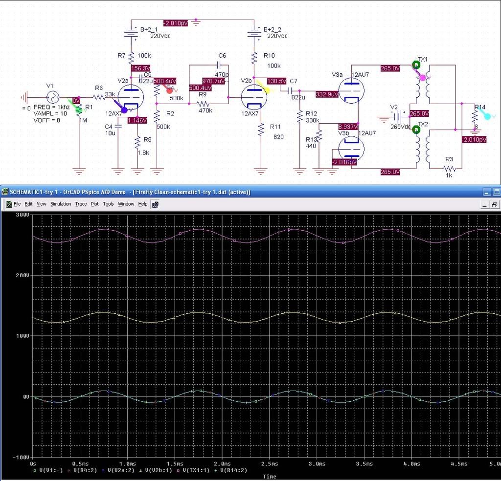
Well, I corrected the values of R1 and R3, and adjusted the voltage down to 0.1V and it crashes after 25ns.
I'm going to have to dig into this.............
Thanks for the comments and help!Comment
-
How does PSpice interpret resistance value entered as 1M, 1 Megaohm or 1 milliohm? Some Spice versions require "Meg" for megaohm. Just a thought, Spice I'm using is like that.Aleksander Niemand
Zagray! amp- PG review Aug 2011
Without the freedom to criticize, there is no true praise. -Pierre Beaumarchais, playwright (1732-1799)Comment
-
Originally posted by Alex/Tubewonder View Post
I am not sure about this. I changed the 1M to a 1000k just to be safe.Comment
Comment