Announcement

Collapse
No announcement yet.

74 Fender Bronco Failing Power Tube Cathode Caps

Collapse
X
 
  • Filter
  • Time
  • Show
Clear All
new posts

  • 74 Fender Bronco Failing Power Tube Cathode Caps

    1974 Fender Bronco, which I believe is a Vibro Champ amp that came in a kit with a Mustang guitar.
    The 6V6 cathode cap seems to be the victim of something out of spec in the circuit.
    The 6V6 cathode cap on the schematic is 25uF at 25V. See schematic here:

    http://vibrochamp.org/wp-content/upl...-schematic.jpg

    Here is the amp layout:

    http://ampresource.com/fender/vibroc...764_layout.gif

    Here is the background:
    A few months ago the amp made a few popping noises and stopped working. A friend brought it to me to have a look at. I found a failed cathode cap inside. Off the single
    6V6 power tube. I tested the 6V6 at that time. It seemed to test weak, so I put a new one in.
    I also replaced the original main B+ dropping resistors at that same time with newer metal film ones. I had suspected maybe the
    old 6V6 was going bad ,maybe intermittent shorting. So with a new tube, cathode cap, and new resistor installed, the amp seemed be working fine.
    2 months go by, same symptoms. I have the amp again today, and I am looking at the same failed cathode cap.
    I happened to have a 25uF/50V cap, so I soldered it in place. Fired up the amp. As amp warmed up cathode cap started smoking. I shut the amp power off. Cap
    is very hot to touch. Let it cool. Put DMM on DC voltage setting on cap lead. Turned on the amp again. Watched the voltage start climbing. I shut off the power off
    as the voltage reached 62V DC. Spec is 21V on the schematic.

    I know enough to get around in the amp, but I am not trained in amp repairs. I am self taught. I have a few questions, if you can help I appreciate it.

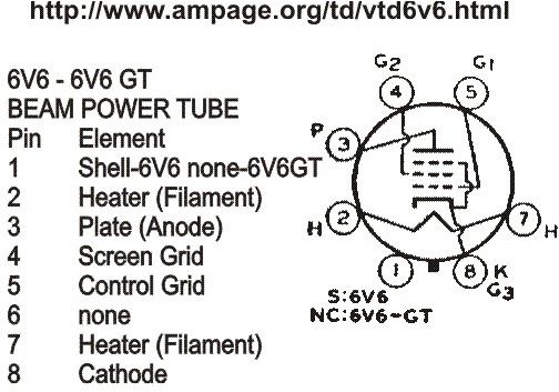
    Looking at a 6V6 pinout diagram, It appears pins 5 (control grid) and 8 (cathode) are connected. Is this correct? Is the voltage for 6V6 pin 5 coming off V1 12AX7 pin 6? The layout shows 200V off this pin. Then a 220K resistor to ground. Does this resistor drop the 200 volts here down to 21V as measured on pin 8 of 6V6? I am wondering if this 220K resistor might be
    the culprit. I better go measure it.

    Any tips appreciated. This is good practice for me. Thanks.

  • #2
    The .02 cap between pin 6 of V1 blocks DC from getting to the 6V6 grid. There should be NO DC voltage on pin 5 of the 6V6. The 220k is a voltage divider to send some of the signal to ground so the 6V6 doesn't get overdriven too badly.
    The cathode is internally connected to the Supressor grid; there are no internal or external (I hope!) connections to pin 5 of the 6V6.

    I'd check that 470R cathode resistor, along with every other resistor in the amp - carbon comp resistors can drift WILDLY with age. What kind of 6V6 did you put in to replace the old one? New tubes can be all over the map regarding specs, and may need the bias resistor adjusted...

    It's a simple amp; you'll get it!

    Justin

    Edit: I bet the B+ in YOUR amp is probably closer to 420-430V, not the 360 on the One you show... look for an AB764…
    Last edited by Justin Thomas; 04-01-2016, 04:06 AM.
    "Wow it's red! That doesn't look like the standard Marshall red. It's more like hooker lipstick/clown nose/poodle pecker red." - Chuck H. -
    "Of course that means playing **LOUD** , best but useless solution to modern sissy snowflake players." - J.M. Fahey -
    "All I ever managed to do with that amp was... kill small rodents within a 50 yard radius of my practice building." - Tone Meister -

    Comment


    • #3
      STOP WHAT YOU ARE DOING. You either have a serious miswire, or you are misreading the schematics.

      No pin 5 is NOT connected to pin 8.

      Let's use proper terms. The SIGNAL from pin 6 of the 12AX7 comes through the 0.02uf cap and to the grid of the 6V6, pin 5. NO DC passes through that 0.02 cap unless it is shorted or super leaky. That is the purpose of the cap, blocking DC. The 220k grid resistor should have no DC across it at all. In practice, there may be a tiny bit for reasons we can discuss elsewhere. Pin 8 gets its voltage entirely by the voltage drop across the cathode resistor, 470 ohms. Ohm's Law tells us that amount. Mr. Ohm tells us that 21v across a 470 ohm resistor means 44 milliamps of current should be flowing through it.

      If you have actually wired pins 5 and 8 together, then you have killed any bias the tube might generate, allowing the tube to freely run away with itself. As the current goes up and up, the voltage across the 470 ohm resistor goes up and up too. That is Ohm's Law again. So when it gets up to 60v, I don't doubt the caps fail.

      I'd like to see a data sheet for 6V6 that has pins 5 and 8 linked together.

      Look at the layout you posted, pin 8 connects over to the part board where it sees the 470 ohm and the cap to ground. No connection to pin 5 anywhere there. Now look at pin 5, it connects to point X. Point X is along the top of the part board a little right of center. The point X thing is just a shorthand for the two places being connected. Saves them drawing wire lines all over the place. Note that point X up there is your 220k to ground and the cap back to pin 6 of the preamp tube.

      If you have pins 5 and 8 wired together, REWIRE it correctly. Follow the layout drawing.

      The Bronco may be identical to the Vibro Champ, but we might as well use the real schematic:
      http://bmamps.com/Schematics/fender/bronco_aa764.pdf

      Is your amp in fact an AA764? The AB764 had different voltages. Note also the AB764 had a small stability cap between pins 5 and 8. If your amp has one of those and it is shorted, that would explain a 5 to 8 connection.

      http://bmamps.com/Schematics/fender/...b764_schem.pdf

      And one last note, if this worked for a couple months, don;t rule out simple tube failure. The two month old 6V6 could have failed. ANy tube can fail at any time.
      Last edited by Enzo; 04-01-2016, 04:11 AM. Reason: Simul-post with Justin
      Education is what you're left with after you have forgotten what you have learned.

      Comment


      • #4
        Thanks for your comments so far. I do believe I have an AB764 Bronco. There is a small 330 pF cap across pins 5 and 8 on the power tube. This is why I figured they were connected.
        At any rate, if that 330 pF cap across pins 5 & 8 has failed, can I clip it out to test? It's absent from the AA764 circuit anyway.

        When I looked at this 6V6 pin out image below, pins 5 and 8 look connected to me. As mentioned, learning here, but parts 5 look and 8 look like they touch to me.


        I have measured all resistors so far that don't have a cap across them. Only one that looks badly out of spec is the negative feedback resistor. The 470 ohm cathode cap off the
        6V6 is new. I installed it 2 months ago and upgraded it to a 5W. The tube that I put in 2 months ago was a new EHX made in Russia. It does now test poor in my tube tester.
        I have a new JJ 6V6S that tested strong in same tester.

        Comment


        • #5
          Pulled caps out where in parallel with resistors to get accurate measurements. 470 ohm 5W I installed off 6V6 pin 8, 2 months ago is dead. It's only 2 months old. I assumed it was still good. Apparently not.
          I checked continuity through 330 pF cap across pins 5 and 8. Nothing, so with limited test gear, I think I can assume that little cap is ok.

          I suppose it's possible maybe I had a failing tube here? Even though it was new 2 months ago also. Cooked 470 cathode resistor maybe, then cap failed?

          Comment


          • #6
            Cap likely failed from voltage, resistor likely failed from excess dissipation. Too much current through it overheated it. yes, a failed tube seems likely still.

            Look again at the tube picture. Pin 8 is the cathode and is also internally connected to grid 3. There is no external grid 3 connections. But look at the line from pin 8 up to grid 3, it hops OVER the pin 5 wire. That is what the little hump in the line is for. Also note the same thing as the poin 4 wire hops over the pin 3 wire inside the tube. Pin 5 ONLY connects to the control grid, nothing else. Wire 8 hops over wire 7.

            yes if the 330pf cap from 5 to 8 doesn;t measure shorted it likely isn't, though you can disconnect one end to be sure it makes a difference or not. And think about this, if pins 5 and 8 were connected together, then a cap going the same place would do nothing, it would be shorted across by that connection.

            One thing to keep in mind: it isn;t about the parts, it is about the circuit. You measured the NFB resistor and found it "out of spec". Not really. First, resistors really don;t go low with age, they usually either go high or just open altogether. Unless it turns to charcoal, there really isn;t a way for a resistor to go low in resistance. I am betting your out of spec resistor measured really low instead of 2700 ohms, right? Did you get something like 45 ohms?

            Look at the circuit, the 2700 ohm resistor connects at one end to the output transformer secondary. It may say 3.2 ohms there, but the winding itself has close to zero ohms resistance. 3.2 ohms is the IMPEDANCE. SO in essence we can consider that end of the 2700 ohm to be grounded. Now look where the other end goes. It connects to a 47 ohm resistor to ground. Since the other end was already grounde, this means the 2700 ohm resistor has the 47 ohm resistor in parallel with it. 47 ohms in parallel with 2700 ohms makes about a 45 ohm total resistance. Did I come close?

            Whenever you measure parts in circuit, you always have to consider the rest of the circuit. The 220k to ground from pin 5 of the power tube should measure about 220k, since the top end is wired to a cap and a tube grid, so ther is NO DC path from there, and thus no parallel path for resistance.

            You can do this test: Pull the 6V6 and leave it out. Now power up the amp. Does any DC voltage now appear at pin 8? SHould stay at zero. Also pin 5, it should also stay at zero. If either one shows DC voltage, you have further problems. One possibility would be the "conductive eyelet board" problem.
            Education is what you're left with after you have forgotten what you have learned.

            Comment


            • #7
              Originally posted by keithb7 View Post

              When I looked at this 6V6 pin out image below, pins 5 and 8 look connected to me. As mentioned, learning here, but parts 5 look and 8 look like they touch to me.


              .
              The 6V6 'image' shows pin 8 & pin 6 tied together.
              It just so happens that pin #6 does not have a designator because it is an internal (to the tube) connection.

              Comment


              • #8
                Excellent information. Thank you very much for taking the time to write it out Enzo. You nailed it exactly on the NFB resistor. You explained it great. It makes sense that a resistor can't offer less resistance, only more.

                I understand the hump in the lines where lines cross over in the tube pin out diagram. The way it's drawn was a little confusing to a rookie.

                I'll replace cathode cap, resistor, 6V6 and check bias. Thanks again.

                Comment


                • #9
                  I thought beam power tetrodes (like 6V6) didn't have a surpressor grid?

                  Comment


                  • #10
                    Frus,

                    Good point! Maybe they should quit putting it in all the tube diagrams? I mean, the designator beside pin 8 of EVERY 6L6/6V6 data sheet I've seen says "K/G3" so...

                    Justin
                    "Wow it's red! That doesn't look like the standard Marshall red. It's more like hooker lipstick/clown nose/poodle pecker red." - Chuck H. -
                    "Of course that means playing **LOUD** , best but useless solution to modern sissy snowflake players." - J.M. Fahey -
                    "All I ever managed to do with that amp was... kill small rodents within a 50 yard radius of my practice building." - Tone Meister -

                    Comment


                    • #11
                      Originally posted by frus View Post
                      I thought beam power tetrodes (like 6V6) didn't have a surpressor grid?
                      The 6V6 is a beam tetrode.

                      Of coarse it has a suppressor grid.

                      The beam forming plates.

                      https://en.wikipedia.org/wiki/6L6

                      Comment


                      • #12
                        I put in a new 800 ohm 5 watt cathode resistor, and upped the capacitor to 25 uf/50V. Lowering the bias.
                        Plate voltage is up now as a result to 435V. I have 32 V on the cathode cap. Based on some internet calculation steps I have 40 ma off 6V6.
                        Still seems high to me, maybe my math is out. Using same math with original 470 ohm resistor, and earlier 418 plate voltage there was 58 mA off the 6V6.

                        At any rate, the amp sounds great as it is now. Makes sense to be how the hot bias earlier maybe cooked a tube, causing the 470 ohm bias resistor to fail.
                        Upping voltage and amps, causing cathode cap to pop. Sound clip of amp last night.

                        https://youtu.be/A8b07BLuYUk

                        Comment


                        • #13
                          Sounds great! Much cleaner than mine... where's the knobs set to, and what's it sound like on 10???

                          Justin
                          "Wow it's red! That doesn't look like the standard Marshall red. It's more like hooker lipstick/clown nose/poodle pecker red." - Chuck H. -
                          "Of course that means playing **LOUD** , best but useless solution to modern sissy snowflake players." - J.M. Fahey -
                          "All I ever managed to do with that amp was... kill small rodents within a 50 yard radius of my practice building." - Tone Meister -

                          Comment


                          • #14
                            With BIAS set as it is now, volume on 10 offers a little break up but not lots.
                            Knob settings in video clip are:
                            Volume 4
                            Treble 5.5
                            Bass 8.5

                            Comment

                            Working...
                            X