1974 Fender Bronco, which I believe is a Vibro Champ amp that came in a kit with a Mustang guitar.
The 6V6 cathode cap seems to be the victim of something out of spec in the circuit.
The 6V6 cathode cap on the schematic is 25uF at 25V. See schematic here:
http://vibrochamp.org/wp-content/upl...-schematic.jpg
Here is the amp layout:
http://ampresource.com/fender/vibroc...764_layout.gif
Here is the background:
A few months ago the amp made a few popping noises and stopped working. A friend brought it to me to have a look at. I found a failed cathode cap inside. Off the single
6V6 power tube. I tested the 6V6 at that time. It seemed to test weak, so I put a new one in.
I also replaced the original main B+ dropping resistors at that same time with newer metal film ones. I had suspected maybe the
old 6V6 was going bad ,maybe intermittent shorting. So with a new tube, cathode cap, and new resistor installed, the amp seemed be working fine.
2 months go by, same symptoms. I have the amp again today, and I am looking at the same failed cathode cap.
I happened to have a 25uF/50V cap, so I soldered it in place. Fired up the amp. As amp warmed up cathode cap started smoking. I shut the amp power off. Cap
is very hot to touch. Let it cool. Put DMM on DC voltage setting on cap lead. Turned on the amp again. Watched the voltage start climbing. I shut off the power off
as the voltage reached 62V DC. Spec is 21V on the schematic.
I know enough to get around in the amp, but I am not trained in amp repairs. I am self taught. I have a few questions, if you can help I appreciate it.
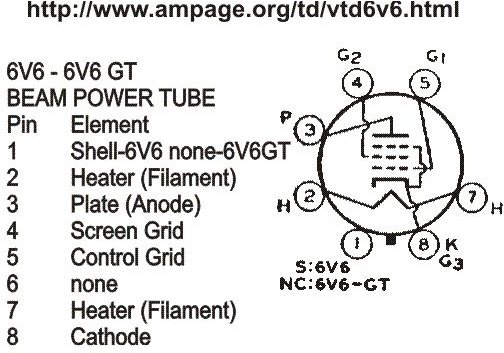
Looking at a 6V6 pinout diagram, It appears pins 5 (control grid) and 8 (cathode) are connected. Is this correct? Is the voltage for 6V6 pin 5 coming off V1 12AX7 pin 6? The layout shows 200V off this pin. Then a 220K resistor to ground. Does this resistor drop the 200 volts here down to 21V as measured on pin 8 of 6V6? I am wondering if this 220K resistor might be
the culprit. I better go measure it.
Any tips appreciated. This is good practice for me. Thanks.


 I mean, the designator beside pin 8 of EVERY 6L6/6V6 data sheet I've seen says "K/G3" so...
Comment