Announcement

Collapse
No announcement yet.

Anyone know what the "tiny terror" circuit is?

Collapse
X
 
  • Filter
  • Time
  • Show
Clear All
new posts

  • Voltages

    Originally posted by Thomeeque View Post


    Original is around 180VAC IIRC, so I'd use those 164VAC. It should be still in usable area with just slightly lower power, which is IMO good thing


    Good luck, T.
    Hello,

    finally I read the entire post, still I have a doubt about the power trafo.
    Before in this post, a schematic has been posted. The schemo showed voltages of:
    -A: 325V
    -B: 320V
    -C: 290V
    -D: 265V

    Now you say that A = 180V.

    1) Which is correct??
    2) Can that difference be due to different versions of the OTT??
    3) If you know the A voltage, is there a way to calculate B, C and D without measuring or simulate with Spice??
    4) How have been calculated the voltages in the previous example??

    Comment


    • Hey there,

      does anybody have a schematic of the Dual Terror so far? - I´ve read some speculations that it is basically two Tiny Terrors (even two PIs!) with just no bright cap on the fat-channel.

      Can anybody confirm that?

      Cheers
      Konny
      Crank it up! - Go Shake, Rattle & Roll

      Comment


      • Originally posted by ciambom View Post
        Hello,
        Hi! Sorry, I have missed this post for some reason It's probably passé for you now, but I'll answer anyway..

        Originally posted by ciambom View Post
        finally I read the entire post, still I have a doubt about the power trafo.
        Before in this post, a schematic has been posted. The schemo showed voltages of:
        -A: 325V
        -B: 320V
        -C: 290V
        -D: 265V
        These are DC voltages measured in 15W mode.

        Originally posted by ciambom View Post
        Now you say that A = 180V.
        This is AC (RMS) voltage before full-wave rectification and filtering for 7W mode.

        Simplified VAC to VDC conversion formula for this situation is: VDC = sqrt(2)*VAC = 1.414*VAC

        So 325VDC at A means, that there's 230VAC at rectifier (D1-D4) input

        and

        180VAC at rectifier input means 255VDC at A. Actually I'm not sure about those 180VAC, this may not be accurate value.

        For more read e.g. Rectifier - Wikipedia, the free encyclopedia

        Originally posted by ciambom View Post
        3) If you know the A voltage, is there a way to calculate B, C and D without measuring or simulate with Spice??
        You could try to recalculate it by using 325:320:290:265 ratio, it won't be perfect but maybe good enough - why do you need it?

        Originally posted by ciambom View Post
        4) How have been calculated the voltages in the previous example??
        What example?

        T.

        Comment


        • Hi Thom,

          you're right: time has passed and now many aspects are clear.
          However thank you for the answer.
          I'm read to build the parts and bulit it, I only would know your opinion about:

          1) power transformer: VT1185

          Valve Transformer VT1185

          this trafo it's amazing, look at the current capability

          I'm not interested in 7W mode, so this should be perfect.
          Hammond just makes trafos with center tap and very poor current capability...

          2) output transformer: Hammond 1760E

          Tube-Town Online-Store - Hammond 1760E Fender OT 125A10B / 022913 UPGRADE Princeton ha1760e

          it should work, but it would be a "Fender style" trafo mounted in a TT, what do you think about??

          3) circuit: I made a 2 layers PCB design with a ground plane. Do you see problems with it?? A star grounding would be better?

          Thanks,
          Marco

          Comment


          • Originally posted by ciambom View Post
            Hi Thom,

            you're right: time has passed and now many aspects are clear.
            However thank you for the answer.
            I'm read to build the parts and bulit it, I only would know your opinion about:

            1) power transformer: VT1185

            Valve Transformer VT1185

            this trafo it's amazing, look at the current capability

            I'm not interested in 7W mode, so this should be perfect.
            Hammond just makes trafos with center tap and very poor current capability...
            I believe that you *could* go with Hammond PT 260E (225-0-225V/100mA) because thanks to the full-wave rectification on center-tapped transformer (where each winding works only for 50% of the cycle) you would get 200mA effectively, but there's no reason really - VT1185 looks like it gives what you need (with nice reserve) and is cheaper.

            What mains voltage you will use?

            Originally posted by ciambom View Post
            2) output transformer: Hammond 1760E

            Tube-Town Online-Store - Hammond 1760E Fender OT 125A10B / 022913 UPGRADE Princeton ha1760e

            it should work, but it would be a "Fender style" trafo mounted in a TT, what do you think about??
            Looks perfect to me!

            But "Fender style" trafo mounted in a TT question is a way below my discrimination ability, I'm far from being such an expert to answer anything valuable here

            Originally posted by ciambom View Post
            3) circuit: I made a 2 layers PCB design with a ground plane. Do you see problems with it?? A star grounding would be better?
            Again, I don't think I can answer this due to my limited knowledge. Proper ground plate can probably work as good as proper star grounding, but you don't see it much in tube
            amps (e.g. original OTT uses 2 layers PCB without ground plate), maybe it is more inclinable to parasite capacitance issues? I would go with star grounding probably.

            Originally posted by ciambom View Post
            Thanks,
            Marco
            My pleasure, please don't forget to show us result when your TT is done (or even soon )

            T.

            Comment


            • Originally posted by Thomeeque View Post
              I believe that you *could* go with Hammond PT 260E (225-0-225V/100mA) because thanks to the full-wave rectification on center-tapped transformer (where each winding works only for 50% of the cycle) you would get 200mA effectively, but there's no reason really - VT1185 looks like it gives what you need (with nice reserve) and is cheaper.

              What mains voltage you will use?


              Looks perfect to me!

              But "Fender style" trafo mounted in a TT question is a way below my discrimination ability, I'm far from being such an expert to answer anything valuable here


              Again, I don't think I can answer this due to my limited knowledge. Proper ground plate can probably work as good as proper star grounding, but you don't see it much in tube
              amps (e.g. original OTT uses 2 layers PCB without ground plate), maybe it is more inclinable to parasite capacitance issues? I would go with star grounding probably.


              My pleasure, please don't forget to show us result when your TT is done (or even soon )

              T.
              I will use the 240Vac primaty for the main, and the 260Vac for the secondary High voltage, it will be a little higher than the original TT (250Vac) but later I'll put a 150ohm 6W cathode resistor on the EL84s to keep the tubes a little more quiet.

              Meanwhile I found another OT which seems more suitable for the "little bastard", I think I'll go with that:
              18W push pull output transformer

              For sure I will inform you as soon as I will complete it.

              Stay rock,
              M

              Comment


              • Problems

                Originally posted by Thomeeque View Post
                I believe that you *could* go with Hammond PT 260E (225-0-225V/100mA) because thanks to the full-wave rectification on center-tapped transformer (where each winding works only for 50% of the cycle) you would get 200mA effectively, but there's no reason really - VT1185 looks like it gives what you need (with nice reserve) and is cheaper.

                What mains voltage you will use?


                Looks perfect to me!

                But "Fender style" trafo mounted in a TT question is a way below my discrimination ability, I'm far from being such an expert to answer anything valuable here


                Again, I don't think I can answer this due to my limited knowledge. Proper ground plate can probably work as good as proper star grounding, but you don't see it much in tube
                amps (e.g. original OTT uses 2 layers PCB without ground plate), maybe it is more inclinable to parasite capacitance issues? I would go with star grounding probably.


                My pleasure, please don't forget to show us result when your TT is done (or even soon )

                T.
                Hi Thom,

                finally I did it, but I have a couple of problems:
                1) if I rise the gain up to nine/ten o'clock the amp start to fizz at very high freq, the sound stop rise the gain&volume and the resulting sound is a mix between the guitar signal and the fizz. If I play a chord, the wave doesn't end but is broken by the fizz.
                2) if I turn clockwise the tone pot, the sound progressively looses volume until turning completely-off, I connected the tone pot like your amp: before master volume section and connecting only the pins 1 & 2, the pin 3 is unconnected.
                Erroneusly I buyed a dual gang-tone pot, but I use just one-half leaving the other half completely connected to ground.

                If you have an idea of what could be..I will be grateful!!
                (I could send you the schematics and some fotos if you want).

                Thanks,
                Marco

                Comment


                • Tone control issues

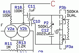
                  Originally posted by Thomeeque View Post
                  Do you mean like this:


                  ?

                  I did implement it this way too, it seemed more logical to me and it works well.

                  I wonder if AdmiralB's scheme is correct at this point, but I cannot check it, I don't have access to original OTT..

                  T.
                  I used this way for my build, but it seems ineffective, which pin is connected to C11? and which pin is leaved unconnected??

                  Comment


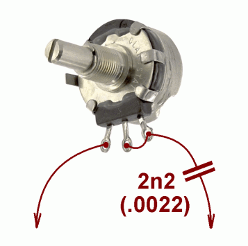
                  • Originally posted by ciambom View Post
                    I used this way for my build, but it seems ineffective, which pin is connected to C11? and which pin is leaved unconnected??
                    Wire it this way, it's IMO best:


                    It does not matter which wire goes to C11 and which to C10 plus C12 (2n2) could intterrupt the other wire, it does not matter as well..

                    Good luck, T.

                    Comment


                    • Originally posted by ciambom View Post
                      Hi Thom,

                      finally I did it, but I have a couple of problems:
                      1) if I rise the gain up to nine/ten o'clock the amp start to fizz at very high freq, the sound stop rise the gain&volume and the resulting sound is a mix between the guitar signal and the fizz. If I play a chord, the wave doesn't end but is broken by the fizz.
                      2) if I turn clockwise the tone pot, the sound progressively looses volume until turning completely-off, I connected the tone pot like your amp: before master volume section and connecting only the pins 1 & 2, the pin 3 is unconnected.
                      Erroneusly I buyed a dual gang-tone pot, but I use just one-half leaving the other half completely connected to ground.

                      If you have an idea of what could be..I will be grateful!!
                      (I could send you the schematics and some fotos if you want).

                      Thanks,
                      Marco
                      Hi Marco!

                      Ad 1 = parasitic oscillation - this is a common issue with tube amps, high-gain tube circuits are very sensitive and you have to be careful when building one. There is some unwanted feedback in your circuit leading to self-oscillation. Feedback is either electro-magnetic (one part /e.g. output transformer/ works as an transmitter and one part /e.g. input capacitor, input tube../ works as an receiver) or electrical, typically transfered via supply or ground wires. To detect the first case try to tune amp slightly above the border where self-oscillation starts and then tap by some isolated (wood) stick to parts and listen, if tapping on some part affects the oscillation. The other case is more complicated to detect. Let's check the first one first.

                      Note: I'm not expert on this at all, it's just the way I understand it and what I would try - google for parasitic oscillation in tube amps to get more precise/rich/correct answer..

                      Ad 2 - dual pot does not matter. You must have made some mistake when wiring the tone pot - either you have not used C12 capacitor in series with the pot or you have used wrong (much bigger) value of this capacitor (it should be 2.2nF = 0.0022uF).

                      Good luck, T.

                      PS: Yes, hi-res photos and schema could be very helpful here.
                      Last edited by Thomeeque; 12-17-2010, 03:30 PM.

                      Comment


                      • Originally posted by Thomeeque View Post
                        Hi Marco!

                        Ad 1 = parasitic oscillation - this is a common issue with tube amps, high-gain tube circuits are very sensitive and you have to be careful when building one. There is some unwanted feedback in your circuit leading to self-oscillation. Feedback is either electro-magnetic (one part /e.g. output transformer/ works as an transmitter and one part /e.g. input capacitor, input tube../ works as an receiver) or electrical, typically transfered via supply or ground wires. To detect the first case try to tune amp slightly above the border where self-oscillation starts and then tap by some isolated (wood) stick to parts and listen, if tapping on some part affects the oscillation. The other case is more complicated to detect. Let's check the first one first.

                        Note: I'm not expert on this at all, it's just the way I understand it and what I would try - google for parasitic oscillation in tube amps to get more precise/rich/correct answer..

                        Ad 2 - dual pot does not matter. You must have made some mistake when wiring the tone pot - either you have not used C12 capacitor in series with the pot or you have used wrong (much bigger) value of this capacitor (it should be 2.2nF = 0.0022uF).

                        Good luck, T.

                        PS: Yes, hi-res photos and schema could be very helpful here.
                        Hi Thom,

                        I'm sure it's a problem of V1.
                        I put a passive serial fx-loop in the amp, so I connected the guitar at the Return jack and play bypassing V1. The sound was clean and loud without noise even with the volume at max. If I turn-on the gain pot, the noise starts but it doesn't affect the signal, it's just added to the signal.
                        I tried to tap the tubes, trafos and pots with a pecil while the amp was fizzing but the taps didn't affect the noise, so I think it's a matter of electrical feedback.. sigh

                        Well.. I attach my schematic which is almost the same of yours.
                        My schematics only contains PCB elements, so you won't see potentiometers, jack connectors, trafos, switches and the first filter capacitor (100u), but only solder pads to connect them by wires.

                        The P1 dual pot, the input jack and fx-loop jacks are completely connected by shielded cables. Later I will attach photos.
                        Attached Files

                        Comment


                        • Tiny Terror Transformer - Overpowered?

                          Can anyone give me some thoughts on a power transformer for a Tiny Terror? I am building a clone and I think I just got one that may be overpowered. I picked up a Hammond 270DAX that has a 260 volt secondary. I bought this one after checking the output of a friend's Tiny Terror (that showed 252 volts on the High output). I just saw on this forum that they actual voltage off the secondary should be around 230 volts and that it would be better for this to be too low rather than too high.

                          So the question is - Would a 260 Volt transformer in fact be too high or is that considered within a reasonable tolerance? Would increasing the Cathode resistor do anything to offest this or would that open a whole can of worms down the power rail?

                          Thanks to anyone who has thoughts. And a general thanks to Thomeeque. We have all learned a ton from you and I for one appreciate it!

                          Comment


                          • Originally posted by Ivory Tower View Post
                            So the question is - Would a 260 Volt transformer in fact be too high or is that considered within a reasonable tolerance? Would increasing the Cathode resistor do anything to offest this or would that open a whole can of worms down the power rail?
                            The specs say the max EL84 plate voltage is 300V +/- 10% but many manufacturers build amps with plate voltages of 340V or more, so I don't think you will have reliability problems.
                            The cathode res should be increased to increase the tube life, I put 150ohm.
                            You can find a detailed discussion on it at the beginning of this thread.

                            Comment


                            • Thanks Ciambom!

                              Does anyone have details on using a "dropping resistor" to reduce the voltage coming off a power transformer? I do want to try and drop the voltage from the 364 volts DC closer to the 325 that the design calls for (note I am talking about the "A" power rail, not the Plate voltage, per se). My (somewhat limited) understanding of dropping rsistors is that I could add one in series just after the output of the Rectifier bridge to get this voltage drop. I ran a quick and dirty analysis in Spice and it seems that a 10k (5W) resistor would drop the voltage just about right.

                              So the question: Is the process of adding a "dropping Resistor" as simple as this. Does anyone have this circuit modelled in spice? I'd love the file of that if anyone has one.

                              Any thought would be appreciated!Thanks,
                              Mike

                              Comment


                              • It sounds good!!

                                Finally I fixed my problem, the oscillation was due to a bad-designed pre-amp section on the PCB. The ground plane was a bad choice, it put a lot of noise on the pre-amp circuit. The noise was suppressed by wiring this part of the circuit.

                                Now it sounds good!!

                                Comment

                                Working...
                                X