Your current calculations are off by a factor of 1000
It's amper?s not miliamper?s....
Aleksander Niemand Zagray! amp- PG review Aug 2011
Without the freedom to criticize, there is no true praise. -Pierre Beaumarchais, playwright (1732-1799)
Alex, thanks for pointing out the faux par..must have been having a senior moment.
I had dropped in references to mA instead of A in certain parts of the equations, where there shouldn't be.
i.e (0.0395mA) should have read 0.0395A or 39.5mA
Please note the results are actually correct with regards the Plate wattage as shown, its was just committing the calculation process to the article that was in error.
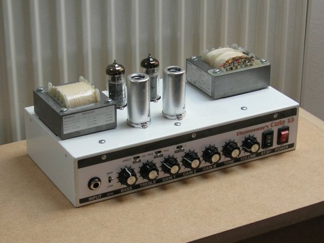
I have finished chassis+electronic part of mine clone before a while, and after some tweaking I'm really happy with the actual results (even it's not perfect yet and I still have some tweaks on schedule)..
As you can see, it's not 1:1 clone (there's DC for ECC83 filaments, switchable 2-band EQ, Sensitivity and Boost switch, direct PA input, two simple Gain pots instead dual one and TT/Marshall PI mode switch), I have wanted more versatile amp, but it's still switchable to almost 1:1 TT circuitry (and honestly this mode /with Marshall PI mode/ so far rules ).
So what you say?
Btw. DIODES switch = PI mode switch I have decided to change my original idea, when labels were done and placed already
And I still have to design and order top and bottom covers.
Last edited by Thomeeque; 07-09-2008, 08:09 PM.
Reason: details..
Excellent job on metal work and transformers. OT with label listing winding details, cool old school touch. Really, really nice.
Now to a couple questionable points:
*how is the sub panel with pots and switches grounded?
**PSU board: I'm a bit worried the isolation distances between tracks are to small and you may get arcing there.
***Boost switching arrangement can be a source for loud pops. It's better to have a large resistor in series with each cap and short the resistor for boost function.
Who does your chassis? I might have a job for them. Please PM me with info.
Aleksander Niemand Zagray! amp- PG review Aug 2011
Without the freedom to criticize, there is no true praise. -Pierre Beaumarchais, playwright (1732-1799)
*how is the sub panel with pots and switches grounded?
subpanel has conductive connection with main chassis (which is grounded to wall) - but only by screws, not wired, bad idea? Is it about security? Btw. pots are plastic, only back covers are metallic, they are all connected and grounded by one wire to PA ground (on Volume pots)
**PSU board: I'm a bit worried the isolation distances between tracks are to small and you may get arcing there.
yes, especialy those psychedelic shielding swirls were probably stupid idea (it even crossed my mind when drawing PCB if there should not be more space between tracks, but I've seen gutshots of EH Black Finger and they have even smaller distances between high voltage tracks and ground).. OK, so far I have not any problem with arcing - should I still worry? Can this get worse? Is there something I can do to avoid it with current PCB (isolating varnish?)?
***Boost switching arrangement can be a source for loud pops. It's better to have a large resistor in series with each cap and short the resistor for boost function.
OK, in this case I knew exactly what I'm doing, I have just decided to try it without those resistors for simplicity reasons (it's very tight area around this switch and it would be 4 more resistors there). I don't thing I will switch often later, and even up to now I have not registered any annoying pop.
Last edited by Thomeeque; 07-10-2008, 08:23 AM.
Reason: Poor English :P Formating..
I just built my clone.
In 15W mode anode voltage is 330V, cathode bias resistor 120 Ohms. Bias voltage is 10.3V which means ~12.9W plate dissipation /grid current is ~4mA and is subtracted from calculations/.
In 7W mode I'm adding /via DPDT switch/ a 630 Ohm resistor in series with the HV tap and another 120 Ohm resistor in parallel. Anode voltage is 254V, bias voltage is 6.1V which means ~11.9W plate dissipation.
Things that I noticed. There's no difference in volume levels between 15 and 7W mode. In 7W mode the tone changes but only a bit - nothing drastic.
When gain is past 3 o'clock and Master is at max I'm getting a noise which sounds like a ground loop noise. When gain is at max but Master is around 3 o'clock the noise is almost inaudible. Tried several grounding points but it's still there. Maybe this beast has too much gain and filament hum leaks into the amplified signal?
I would appreciate if you have any ideas how to solve this.
Filaments are AC, dual pots are 1M with different value resistors across them in order to match the original ones. Everything is PCB mount.
I think I may have blown the power transformer on my TT. After playing guitar directly plugged in at moderate volume for about 20 minutes, it started sounding about half as loud somewhat suddenly. Then it came back to normal after I removed and replugged in the speaker wire. Then it began to fade again. I shut it off waited and turned it on and it came back to normal again. Then after a minute it faded again, and then faded out completely.
There was no burning smell or smoking from amp.
Now at this time, I have to mention that I had done a very bad thing. I had another amp (the all tube 5 watt Blackeart with a 16 ohm speaker output) plugged into (with power off) the same 16 ohm 1x12 cab that the TT was plugged into. Thereby probably putting the Blackeart speaker transformer output in parallel with the TT output. I check the resistance of this combination with an ohm meter and it read around 12 ohms. I also checked the resistance of just the Blackheart output and that was about the same !?!?
I openned up the TT and turned it on to see if the tubes were glowing because I thought at 1st maybe it was the tubes. It worked for a minute or so and then faded again. The tubes initailly glowed then the power tubes faded to dark. The preamp tubes still glow even when sound is completely gone and power tubes are dark.
I replaced both power tubes, nothing changed. Put old ones back.
Waited several hours, no sound at all, power tubes dark, preamp tubes glow.
So do you think it is a capacitor in the power supply chain or a section of the transformer that supplies the "glow"?
Next I will try to measure the Xformer voltages I guess. Do the filiments glow with AC directly from Xformer?
Please help if you have any insight into this unfortunate occurrence !!!
Thanks,
Bruce
Last edited by strangebru; 07-11-2008, 02:00 AM.
Reason: left out important fact
I checked the transformer. It gets what it says it should on the secondarys.
I checked the supplies to the tubes: the power tubes get about 320 VDC on 2 pins each, the preamp tubes are getting around 220-250 VDC; and the filaments (I guess) are getting about 6 VAC on all tubes. So I guess the transformer is OK.
I tried the amp again and it worked for a minute or so then died again. I measured the voltages and they were the same as stated above. The power tubes are dark and cold even though they have 320 VDC on them and they are getting 6 VAC. How can that be ?
What does this mean ???
Is that PC board fuse a thermal fuse that's malfunctioning?
I turned amp on full blast and strummed chords (of course there was no sound, because its not working) and measured the voltage on pin 2 (unless I got it backwards, then maybe pin 8) of both power tubes and got about 40VAC on each. With no strumming the voltage is 0.0. But nothing from the speakers. I measured the output of the output xformer under these same (guitar strumming) conditions, and no AC voltage was present. So I guess that this means that the output xformer is shot. Does that sound correct? Is there another test that would prove this outside of buying a new one?
Last edited by strangebru; 07-11-2008, 05:18 AM.
Reason: further findings
So I guess that this means that the output xformer is shot. Does that sound correct? Is there another test that would prove this outside of buying a new one?
Hi!
If there is something wrong with filaments on power tubes (power tubes dark), this can be source of whole problem and you should focus on that at first place!
Now, filaments are powered directly from PT, no capacitor is involved in this problem.
Fuse is not probably involved either, beacuse it's one for all filaments (so even preamp tubes would have to be dark). Plus it's simple fuse - when it burns once, it's burned for good, no way it could recovery..
What can be involved further depends on where exactly did you measured the filaments voltage! Was it on PCB directly on V3 and V4 pins (pin 5 and 4)? If yes, there maybe something wrong with soldering of these pins (try to resolder) or with pins inside socked (it can be rusty for example, try to clean it somehow). If not, measure it directly on V3/V4 pins 4 and 5 first.
If the voltage is not there, check whole path from V3/V4 pins to PT. I would not be surprised if the problem was in bad connection in one of filaments power connectors on PCB (rusty or burnt pins), where twisted black and yellow wires go (these wires distribute current for filaments to all valves - see sjwebb90's pics 1, 2, 3)
I'll continue later..
Last edited by Thomeeque; 07-11-2008, 09:13 PM.
Reason: details..
Is there another test that would prove this outside of buying a new one?
To make simple "global" test of OT you can do following:
- remove power cord from amp
- pull out both power tubes
- plug in speaker (but unplug second amp!! )
- get some small voltage source (e.g. 1.5 Volt battery)
- connect one pole of battery to pin 7 of V3
- touch by second pole of battery pin 7 of V4
- this way you will generate pulse into OT
- you should here pops from speaker by each pulse
Of course, be careful, double-check there's no dangerous voltage on any part you are planning to touch (e.g. pins 7)!
Well, I checked the filament voltages as noted in my post, they are all about 6 VAC. Also, as in my SOS post prior to this I replaced the power tubes, same symtoms. This is a brand new amp, no rust. If you disconnect the wire to you speaker (I know this is not good for more than a few seconds) do your power tubes still light up? I say this, because if the secondary of output xformer is shot, then this would be a similar situation, in that no current goes thru secondary. Therefore no current thru primary, yes? Therefore, tube is doing no work, so its cold?
OK, I will try this, but just a couple of things. Pinout question: how are the pins numbered? Is it clockwise looking down from top, or counter clockwise, or is the convention from loking at the bottom? Also, could I not do this same check by putting battery right on to the primary leads?
Well, I checked the filament voltages as noted in my post, they are all about 6 VAC. Also, as in my SOS post prior to this I replaced the power tubes, same symtoms. This is a brand new amp, no rust. If you disconnect the wire to you speaker (I know this is not good for more than a few seconds) do your power tubes still light up? I say this, because if the secondary of output xformer is shot, then this would be a similar situation, in that no current goes thru secondary. Therefore no current thru primary, yes? Therefore, tube is doing no work, so its cold?
As far as I know glowing of tubes depends only on filaments voltage. Current status of output transfromer (and rest of circuit) has no influence on this! Believe me, if the power tube is dark and cold, there's no voltage on it's filament, period. And because you have tried other pair of tubes with same results, you should check amp. There can be for example cold-soldered joint even on brand new amp or some defect in sockets etc.
Last edited by Thomeeque; 07-11-2008, 11:00 PM.
Reason: clarifying..
OK, I will try this, but just a couple of things. Pinout question: how are the pins numbered? Is it clockwise looking down from top, or counter clockwise, or is the convention from loking at the bottom?
(bottom view, e.g. as you see it on PCB from soldering side)
News flash: You may have been right with your cold solder theory. Its all a little strange though. I measured these filament voltages at 6 VAC right at the tube pins and get 6 VAC. Yet there IS a very bad cold solder on the supply clip to the power tubes. When I press down the amp light up. Well I will fix it right now. Even though it doesn't completely make sense. I'll keep you posted. Thanks.
 Tweet
Tweet


 ).
).
Comment