Ad Widget

Collapse

Announcement

Collapse
No announcement yet.

Anyone know what the "tiny terror" circuit is?

Collapse
X
 
  • Filter
  • Time
  • Show
Clear All
new posts

  • #46
    Originally posted by AdmiralB View Post
    Ask and ye shall...


    Why do you say this? It is neither of those things.
    Hi AdmiralB & others!

    I have two questions to OTT circuitry (OTT.pdf):

    1) What is that switch between + pole of filtering 100uF cap and 150/5W resistor (and "A" line)? Normally I would say that this is the STAND-BY switch, however as I understand it, the "15/7" On-Off-On switch handles STAND-BY as well, so..?

    2) To dual-gang logarithmic VOLUME pot - how critical is tracking quality of the pot-couple at this point of circuit? As I see it, the bad tracking could unballance power tubes (but I have no idea, how "fatal" will be circumstances for the rersultant tone), so I'm just wondering if I should not pick linear dual-gang pot (which has usually better tracking) instead, when I have doubts about tracking quality of pots available to me - thanks to following 220k resistors it will get bit "logarithmic" too (see Better Volume Control), but on the other hand I want to stay as close as possible to original circuitry.

    Thanks, Thmq

    Comment


    • #47
      Originally posted by Thomeeque View Post

      1) What is that switch between + pole of filtering 100uF cap and 150/5W resistor (and "A" line)? Normally I would say that this is the STAND-BY switch, however as I understand it, the "15/7" On-Off-On switch handles STAND-BY as well, so..?
      I had an early amp. The first runs had a DPDT center-on three-position power switch - off, standby, on. The current amps have a three-position power switch that selects either HV tap - or neither, for standby.


      Originally posted by Thomeeque View Post
      2) To dual-gang logarithmic VOLUME pot - how critical is tracking quality of the pot-couple at this point of circuit?
      IMO, not very. I don't think linearity means a whole lot WRT guitar amps.

      Comment


      • #48
        I had an early amp. The first runs had a DPDT center-on three-position power switch - off, standby, on. The current amps have a three-position power switch that selects either HV tap - or neither, for standby.
        OK, this explains "strange" placing of STBY label on the picture below I have not understand up to now Thanks!

        Comment


        • #49
          I don't know if anyone mentioned it but that off-stdby-on switch is called a progressive toggle switch.
          MOJO use to sell them if you need one, but if you wire a standard DPDT switch correctly, it will do the same thing but be OFF in the middle.
          Or... toggle down = standby, toggle in the middle = OFF and Toggle up = AMP ON.
          Bruce

          Mission Amps
          Denver, CO. 80022
          www.missionamps.com
          303-955-2412

          Comment


          • #50
            Originally posted by AdmiralB View Post
            Smith's patent selects different taps on the primary - in practice, one is 120V and the other is around 160V, which when fed 120V gives the result of 120V variaced down to about 90V. It browns out the whole amp, HV, heaters, bias, etc.
            He got a patent for that? My Greytop JMI AC-30 has a switch that does exactly that and I have used it for that purpose. This is a great example of my belief, that many of Smith's "patents" wouldn't stand up in court if someone were to seriously challenge him.

            RE
            Last edited by tboy; 03-16-2008, 02:08 AM. Reason: closed quote tag

            Comment


            • #51
              Originally posted by Steve A. View Post
              Thanks for bringing this up! I have a few Epi Valve Jr's and Tube 30's around and was planning to try out a TT design in one of them. There are so few parts (other than the power supply) that I think it should be fairly easy to design an eyelet board for it- or even use perfboard.
              Steve, all,

              still haven't sorted that little amp of mine out yet - got side-tracked again....

              BUT, regarding cheap little amps as donor fodder - thomann in the EU do a 2/3 price version of the EPI Valve Jr, and now they have a new super cheap combo amp :

              http://www.thomann.de/gb/harley_benton_ga15.htm

              I wonder what circuit this is ?

              Gareth.

              oh their valve jr. is :

              http://www.thomann.de/gb/harley_benton_ga5.htm

              Comment


              • #52
                Hmmm, those Harley's are *sexy*!! Plus that price - it's not much more than a price of material for DIY project! :-O T.
                Last edited by Thomeeque; 03-17-2008, 11:31 PM.

                Comment


                • #53
                  OTT voltage chart

                  Hi guys -
                  If anyone is interested, I can forward the OTT voltage chart, with readings taken from an actual OTT head. Lemme know.

                  Comment


                  • #54
                    Hi! I'm definitely interested! Thanks, Thmq

                    Comment


                    • #55
                      me two! ARe there any suggestions what PT / OT can be used (Hammond ?)

                      Comment


                      • #56
                        Hi,
                        I made a home brew of this one, and lack of top end, was a hinderence.
                        In the end I developed my own schem and moved away from the origional and installed passive Bass and assignable Treble controls.
                        Post your mail address or PM me if you are interested.
                        Cheers,
                        John G

                        Comment


                        • #57
                          Hi guys, yet another new poster here, i bought the tiny terror and all was ok until the gain control went a bit naff, ie at certain positions the output was hardly any at all and completely awfull sounding like a busted speaker, and now my problem as got even worse with no output at all, i have looked around the net but cant find anyone that supplies the a500k dual pot, so any ideas how i can get it up and running without this pot ie, fixed resistance instead perhaps? as i only ever used to like the setting of the gain at about 12 o clock, i guess that would equate to the pots resistance of about 250k? or does it not work like that with the logarithmic side of things? any help would be realy appreciated many thanks stavo......

                          Comment


                          • #58
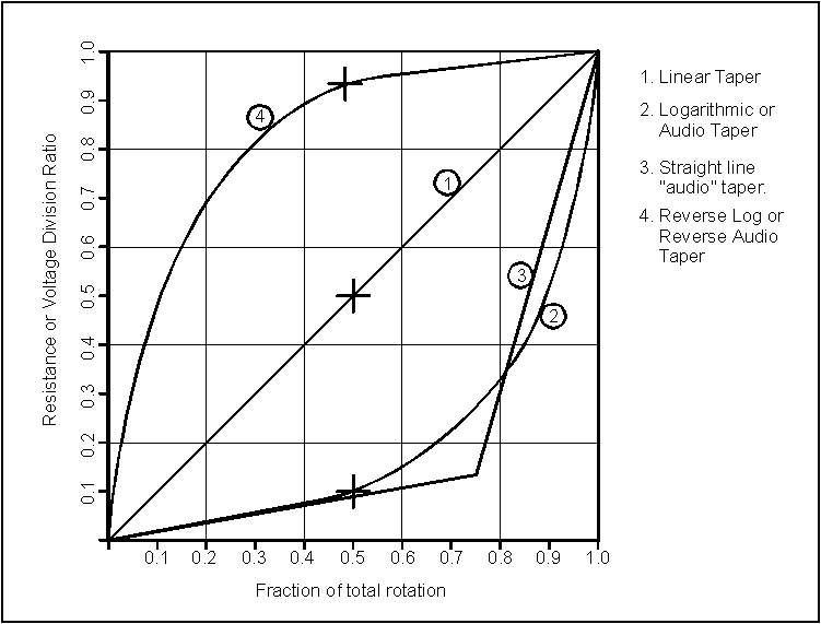
                            Hi Stavo! According to following picture:


                            you should get approximately 90% of original A500k range by using A250K pot + 250k "starting" resistor (0.5 voltage division accords to 0.9 rotation fraction). Your favourite setting (0.5 rotation fraction) accords to 0.1 voltage division, so you will still have big reserve

                            Please note: real pot does not have ideal logarithmic course (curve 2 on pic), so the numbers I wrote above are just approximate, but exact accuracy is not point here. Check whole pot-story here: http://www.geofex.com/article_folder...s/potscret.htm

                            Comment


                            • #59
                              But I'd advice to you to contact Orange first, they should be able to supply exact replacement pot..

                              Comment


                              • #60
                                Originally posted by Thomeeque View Post
                                But I'd advice to you to contact Orange first, they should be able to supply exact replacement pot..
                                Cheers thom for the info, i have just repaired i think? the pot but we have another problem now, i think one of the el84's has gone but i cant work out which one? if i put only one in nothing happens but when i change it to the other (also on its own) it starts to smoke one of the 470 ohm 5 watt resistors i think these two (one for each valve) connected in series are the screen? one tests now only 360 ohms could this be the cause for the smoking of this resistor? or is the valve gone? and the other valve which does nothing is good or what? i dunno i am confused? help!!!! please or anyone, cheers stavo.

                                Comment

                                Working...
                                X