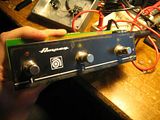
I'm looking for information about what's inside of Ampeg footswitches like the AFP-2 and the AFP-2B. These are fairly simple footswitches that use a 1/4" TRS phone plug to control two features of an amp by completing the ground connection in a circuit. They also contain an LED indicator, so I'm wonder what's inside of them.
I could be wrong, but I don't think that they contain any complicated logic circuits like some of the Mesa footswitches.
Looking at an SVT-2 Pro schematic, my educated guess is that each segment of the footswitch just completes the ground connection between a (+) voltage coming out of the amp and a ground connection, so that the footswitch wouldn't have anything more inside of it than an LED and a current limiting resistor in series with the switch.
Some other amps like the VOX AC30 reissues use footswitches that contain the LED+resistor in the footswitch box, though some other amps dispense with the resistor, only putting the LED in the box. Doing this would have to relocate the current limiting resistor to the innards of the amp itself.
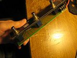
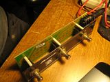
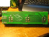
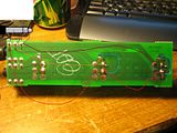
Does anyone have tech info on how the Ampeg AFP-2 and AFP-2B footswitches are wired? A schematic would be appreciated. Even a guts photo would help. Or just a good description. I'd like to build a footswitch box to work with an old SLM-era 2 Pro.
Thanks.
Comment