Announcement

Collapse
No announcement yet.

Why high gain amp use multiple stages but attenuate before driving the next stage?

Collapse
X
 
  • Filter
  • Time
  • Show
Clear All
new posts

  • #16
    Originally posted by teemuk View Post
    Well since Carvin got mentioned....

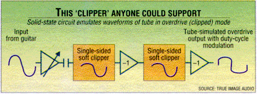
    ...we must not overlook one important part of this topic, which is the importance of making a design that makes pattern of harmonic distortion interactive with signal envelope in preferred manner. When overdriven, many tube preamp designs don't just statically clip tops off from both negative and positive halfwaves, instead the clipping in each stage is usually deliberately designed quite asymmetric. When the stages are capacitively coupled the asymmetry creates gradual DC bias shifts within the gain stages and the bias shift further on creates varying symmetry/asymmetry when the signal is further on clipped. If the gain stage inverts the signal (like typical tube gain stages) the signal asymmetry also leads to duty cycle modulation. As a result we get harmonic pattern of distortion that interacts and changes with note envelope instead of a "static" harmonic pattern where amplitude of each harmonic just rises or decays according to signal amplitude.

    Which gets us to Carvin. Their engineers, like many others, discovered this phenomenon rather quickly after the typical "tubes produce even order and transistors odd order distortion" idea had been proven blatantly incorrect. The following image portrays operating principle of Carvin's tube emulator, which emulates the behavior of few AC coupled triode gain stages one could typically find from a tube guitar preamp.


    The other major part... well it's in those "various filters" but that's another story. ;-)
    This is a very insightful post. I really have to sit on this and think. In the first attached image, Is this the reason why a lot of the high gain amps use the circuit similar to (B) to cut the bass instead of (A)? (B) uses a larger coupling cap of 0.22uF, this gives a longer time constant to create the envelope to get the touch sensitive. In (A), the coupling cap is only 750p, the time constant is so short there is no pumping the DC offset up or down.


    Also, I drew the load line of 12AX7 at +B=340V. I drew 3 load lines:
    1) Blue represents typical Fender with Rp=100K, Rk=1.5K for plate current of about 1.13mA.
    2) Red represents Rp=150k with Rk=3.3k for plate current of 0.7mA.
    3) Orange represent Rp=220K, Rk=3.3K for plate current of 0.7mA.

    I also drew the horizontal lines for grid voltage increment by +/-0.5V and look at the linearity. It is obvious that the output wave form compresses when the plate swing towards +340V. So all the waveforms has a compressed top like what you described.

    From the drawing, if you want asymmetric compression, you should run lower current with smaller Rp so you run and high plate voltage so you get into more of the asymmetrical waveform. But I look at many guitar amps, they run higher Rp like 150K to 220K and plate voltage at 160V to 180V. That seems to be running in more of a linear mode rather than asymmetrical compression. That is doing the opposite of what you described. I experimented with low and high plate voltage, I actually like higher plate voltages.

    Do you have any article on those "various filters"?

    Thanks
    Attached Files

    Comment


    • #17
      Originally posted by Alan0354 View Post
      ...Is this the reason why a lot of the high gain amps ... cut the bass ...
      Someone can probably explain it better in more technical terms but in practice lower frequencies are attenuated before clipping because of this...


      The black waveform represents our signal, which in this case in practice consists of three fundamental frequencies at different amplitudes. These are represented in red, green and blue. Consider the red one as our "bass" frequency, it's wavelenght is enough to exceed the wavelenghts of higher frequency waves.

      Now everything is "ok" if signal is not clipped and different frequencies are simply superimposed to the wave in their proper amplitudes. But now, let's play with a thought that we feed this wave to a clipping circuit that happens to have its clipping threshold right in the "notch" point of that waveform. Output from such clipper stage is pretty much a square wave that follows the duty cycle of the lowest frequency (red waveform), and although wealth of harmonics are generated due to distortion we also "lose" all high frequency signal content that was originally carried within the signal. A practical term to describe how this kind of clipping generally sounds is... ...well, "farting". If you just hate "note separation" on distorted chords, and if you're really into that 60's fuzz "buzzing" as only distortion tone then this is exactly the recipe, for modern tones its accustomed to low off low end before clipping, often very drastically right below (gulp) mid-range frequencies.

      Older amps sort of took a "middle route": It is not neccessary to amplify the fundamental at "full" amplitude, due to psychoacoustic effects the upper harmonics of the fundamental frequency will also convey the fundamental to the listener. So, they generally rolled down only "some" low end, clean channels of multi-channel setups will also benefit from such approach. If you don't distort, it's usually not neccessary to "thin" the tone. But still, keep in mind that in the days of those "older amps" a treble booster in some form was usually found from the input chain of nearly each rig.

      A wortwhile experiment is to place two graphic EQs before and after some generic distortion pedal, the flatter response the pedal has the better (e.g. a fuzz might be a better option). Experiment with different EQ settings, both pre and post distortion. You will likely find that pre and post distortion EQs will work somewhat "differently" considering the overall tone, and that for "practical", "good" tone there usually are some "unwritten" rules you tend to end up following. Like rolling down lower frequencies before distortion (due to reasons explained) and rolling down higher frequencies post distortion (because the upper harmonics of clipping pretty much always sound nasty). Sometimes designer can cut corners with the latter because typical guitar loudspeaker cabinets have a response that falls entirely down around 5 - 7 kHz.

      Now think about the pre and post frequency responses of some of your favourite settings with that 2xEQ+DST rig and how a designer might implement filters into a practical amp design to achieve a similar response without resorting into building two graphic EQs. ;-)

      Comment


      • #18
        Another thing to consider is that there are several ways to cut low-end response - smaller coupling capacitors, inter-stage filters, and smaller cathode-bypass capacitors.

        Each one cuts low end in a different manner - the coupling capacitor will add a -6dB/octave rolloff, the bypass capacitor will introduce a shelving eq, but you don't have a lot of control over the relationship between the corner frequency and shelving amplitude (because of the fixed value of cathode resistance), and the interstage filter will give you a shelving eq where you can tailor both the frequency and amplitude of the shelf.

        Tailoring the low frequency cutoff is critical to achieving the right distortion tone. You will find that smaller coupling capacitors will tighten up the low end nicely, but will get too "thin" when you get to the point where high gain sounds tight. Cathode bypass caps can be made smaller to achieve a high-freq boost/low freq cut, but you can't usually get enough low end attenuation and keep the corner frequency where you want it. The interstage filtering gives you more control. I have found that it sounds best to use all three of these in each stage to carefully tailor the response.

        In addition to this, careful use of small capacitors across the plate load resistor or from plate to cathode, can be used to tame the high frequencies in each stage to prevent the "box o' bees" tone.

        Comment


        • #19
          Originally posted by teemuk View Post

          Output from such clipper stage is pretty much a square wave that follows the duty cycle of the lowest frequency (red waveform), and although wealth of harmonics are generated due to distortion we also "lose" all high frequency signal content that was originally carried within the signal.
          Thanks for the reply, actually this is not what I was referring to. I understand that if you clip the waveform with high fundamental, the higher harmonics disappeared and you get farting. I am more talking about touch sensitive, the coupling cap got charged up due to high level signal and change the bias of the next stage to create the touch sensitive. If you look at my former post in drawing (A) and (B), they both cut out the lows to avoid farting. The difference is (B) uses 0.022uF as coupling and use RC to cut lows, (A) uses small coupling cap to cut low. Even if you match their frequency characteristics, the sound and the touch is different because of the DC charging of the coupling cap.

          Originally posted by teemuk View Post
          A wortwhile experiment is to place two graphic EQs before and after some generic distortion pedal, the flatter response the pedal has the better (e.g. a fuzz might be a better option).
          Yes, I experimented with that. In fact I put in a full tone stack ala Dumble 97 using trim pots to taylor the pregain equalization to experiment the sound.

          Originally posted by teemuk View Post
          The interstage filtering gives you more control. I have found that it sounds best to use all three of these in each stage to carefully tailor the response.

          In addition to this, careful use of small capacitors across the plate load resistor or from plate to cathode, can be used to tame the high frequencies in each stage to prevent the "box o' bees" tone.
          I have to try the cap from plate to cathode. What is "box o' bees" tone? What size cap do you recommend? Do you use cathode bypass cap for this as if you use a big bypass cap, the cathode is at AC ground and the plate cathode cap is nothing more than cap from plate to ground. I look at Dumbo doing that. But they use 27p with over 1uF of cathode cap, that is not going to do any feedback.

          Thanks

          Comment


          • #20
            I always looked at the "cap across the plate load" as a simple top end bleeder circuit. No feedback considerations. A preamp plate load in a typical circuit is a resistor between the plate and a very low impedance voltage source. That very low impedance is where the frequencies that cap passes make their way to ground. In this light I don't see any significant feedback to consider.
            "Take two placebos, works twice as well." Enzo

            "Now get off my lawn with your silicooties and boom-chucka speakers and computers masquerading as amplifiers" Justin Thomas

            "If you're not interested in opinions and the experience of others, why even start a thread?
            You can't just expect consent." Helmholtz

            Comment


            • #21
              Originally posted by Alan0354 View Post
              The difference is (B) uses 0.022uF as coupling and use RC to cut lows, (A) uses small coupling cap to cut low. Even if you match their frequency characteristics, the sound and the touch is different because of the DC charging of the coupling cap.
              Indeed. The RC circuit wont' only adjust overall frequency response, it also establishes a time constant for dc offset shifts. Referring to my earlier post, this has direct influence on "harmonic generation" during sustained clipping that influences dc offset points.

              Comment


              • #22
                Agree and add:
                Output from such clipper stage is pretty much a square wave that follows the duty cycle of the lowest frequency (red waveform), and although wealth of harmonics are generated due to distortion we also "lose" all high frequency signal content that was originally carried within the signal.
                This is the difference between SS clipping (perfectly described above) and Tube distortion.

                SS will generate harmonics, but they will be perceived as "artificial" , while tubes maintain part of the original guitar voice, enough to recognize them.

                As in: "with SS clipping all guitars sound the same" vs. "with tubes you can identify them".

                A distortion pedal which got justly famous is the Tube Screamer, because although it clips very SS style, symmetrically with diodes, thus squashing original harmonics (the "wiggles" superimposed on the fundamental sinewave as shown by Teemu) , it also mixes some of the original signal with the distorted one.

                It also cuts lows before distortion to the rate of 4k7/.047uF .
                Yes, cuts lows below 720 Hz !!!!
                Juan Manuel Fahey

                Comment


                • #23
                  Originally posted by J M Fahey View Post
                  SS will generate harmonics, but they will be perceived as "artificial" , while tubes maintain part of the original guitar voice, enough to recognize them.

                  As in: "with SS clipping all guitars sound the same" vs. "with tubes you can identify them".
                  I thought the only way to deal with what Teemuk described is to put a high pass filter to lower the amplitude of the low frequency so the original harmonic can show up after clipping. You can do this for both SS and tube and get the same result in this aspect.

                  I thought the difference mainly is triode generates much more 2nd harmonics and less odd and higher harmonics when pushed even before clipping. Transistors are more like pentodes that generate much wider spetrum of harmonics to 7th and beyond. That's what I don't understand why a few guitar amps use pentode as the first stage. I know pentode has higher gain, but it generates much wider spectrum of harmonics.
                  Last edited by Alan0354; 11-11-2014, 04:37 PM.

                  Comment

                  Working...
                  X