Ad Widget

Collapse

Announcement

Collapse
No announcement yet.

So I have been given free reign to gut a Blues Jr and do whatever I want with it

Collapse
X
 
  • Filter
  • Time
  • Show
Clear All
new posts

  • #16
    In your case, I would eliminate the choke just because of its size and cost even if there was an audible improvement in having it. I also expect the audible difference to be very small, although I have not myself tried the JMI-era circuit without the choke. IMO, the downsides far outweigh the potential benefit.

    And also, I would keep the tube rectifier. Korg didn't switch to SS rectifiers for tone but to cut costs and improve reliability. I like sag, so I always build with tube rectifiers.
    But you are working within tighter constraints than I would be (budget, space, and filament current), so keeping the tube rectifier may not be an option for you.

    What you might do is start with diode rectifier and resistor in place of the choke and just leave space for the circuitry to switch over to a tube rectifier and choke if the outcome is not to his liking. It's not like you'll be out a lot of money for trying the diode and resistor option first.
    Comment


    • #17
      I think I'll try the diodes first. Could add a tube later if I felt so inclined.

      This is probably all I need I'm guessing:


      I did see a 6 diode rectifier like on a Twin. Don't know what the difference is...

      ~Semi-No0b Hobbyist~

      Comment


      • #18
        I'm not sure why they used six diodes either, but I'll bet it was a safety measure in case one of them burned out. It might also be for voltage rating.

        Also, for the choke resistor, perhaps you could use a high-wattage wirewound resistor so that you get some of the choke-like behavior.
        Last edited by dchang0; 02-26-2017, 12:15 AM.

        Comment


        • #19
          ok here's a preliminary drawing without a reverb circuit. I'm not quite sure if I got the PI just right. I copied the vox but the bottom part of the PI is where it ties into the channel that I'm omitting. I noticed in a Fender LTP there's a final 47 ohm resistor before ground. Do I need that resistor in place?


          Click image for larger version

Name:	86reverbvox.jpg
Views:	1
Size:	143.2 KB
ID:	844840

          Click image for larger version

Name:	86reverbnoverb.jpg
Views:	1
Size:	592.5 KB
ID:	844841
          ~Semi-No0b Hobbyist~

          Comment


          • #20
            Originally posted by dchang0 View Post
            Ah, yeah, if it's un-repairable, might as well gut it.

            One small amp I have always wanted to build is the Gibson GA-1RVT. It's got reverb AND tremolo in a circuit small enough to stuff into a 5F1 Champ. I have not heard any recordings of it, however, so it may not actually sound all that good. There are larger Gibson circuits you might be interested in building that seem to be well-regarded (and there are recordings of these). This route would be the "bragging rights for a rare circuit and rare tone" approach.

            I used to have a more modern GA30RVS and that was a sweet sounding amp. Always wanted to play around with its 15w hijo
            ~Semi-No0b Hobbyist~

            Comment


            • #21
              Thanks for confirming the GA30RVS sounded sweet. I am even more likely to build one of its related but smaller siblings.

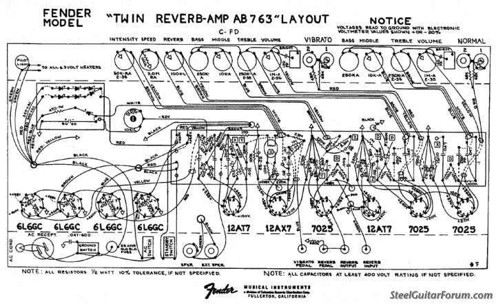
              Here's Rob Robinette's excellent explanation of how the Fender AB763 works. Note that the 47 ohm resistor (along with the 820 ohm at the top) is labeled "NFB (Negative Feedback)" at the top of page 3.

              https://robrobinette.com/images/Guit..._Robinette.pdf

              Given that the AC15 was famously designed without negative feedback, I think you should leave that 47 ohm resistor out.

              I am looking for a Matchless Nighthawk Reverb schematic for you--that is going to be very, very close to what you want. Certainly it will be identical in sections to what you want--it has a master volume and tube reverb. So the only difference will be small tonal tweaks (perhaps they run the EF86 hotter or cooler than the AC15, etc.).

              Comment


              • #22
                Grrrrr. I am finding Matchless DC30, Spitfire, Lightning, and Chieftain Reverb schematics, but no Nighthawk Reverbs!

                There has to be one out there somewhere...

                Here's a video review of the Nighthawk Reverb that you could show him to give him an idea of what he would get:

                https://www.youtube.com/watch?v=Lf1AIAOH8Ls

                This is somebody's Spitfire clone with a modded tone stack. You can double-check your schematics against it. Note that they did not borrow the 47 ohm resistor from the Fender:

                http://www.mhumhirecords.org/DIYpage...eSchematic.bmp

                I believe this is a true-to-original Spitfire schematic:

                https://tornadoalleyfx.files.wordpre...fire_pdf_1.png

                This also does not borrow the 47 ohm NFB resistor from the Fender.

                They both DO have the master volume.
                Last edited by dchang0; 02-26-2017, 05:36 AM.

                Comment


                • #23
                  Originally posted by mort View Post
                  I think I'll try the diodes first. Could add a tube later if I felt so inclined.

                  This is probably all I need I'm guessing:
                  A bridge rectifier like that is fine with the Blues Junior PT but it won't work With a 5F1. The 5F1 needs a two diode full wave rectifier.

                  Comment


                  • #24
                    Originally posted by mort View Post
                    [ATTACH=CONFIG]42508[/ATTACH]
                    I'm not sure that circuit will work too well. It won't have enough gain to drive the PI. The high impedance pentode is trying to drive a 56k slope resistor which could reduce its gain to something like that of a 12AX7 then there's the loss in the tone stack which could be up to 20dB (x10)

                    Comment


                    • #25
                      Originally posted by Dave H View Post
                      I'm not sure that circuit will work too well. It won't have enough gain to drive the PI. The high impedance pentode is trying to drive a 56k slope resistor which could reduce its gain to something like that of a 12AX7 then there's the loss in the tone stack which could be up to 20dB (x10)

                      I borrowed that tone stack from an EF86 channel I built last year. Had some help designing it but it worked very well. It did have the extra 12ax7 in there but it had way more gain than I need in this build. I'm open to suggestion though if it needs tweaked.

                      Click image for larger version

Name:	schematic3add.png
Views:	1
Size:	249.6 KB
ID:	844845
                      ~Semi-No0b Hobbyist~

                      Comment


                      • #26
                        Originally posted by mort View Post
                        [ATTACH=CONFIG]42531[/ATTACH]
                        That one will have a lot more gain. The EF86 is driving a 500k pot not a low impedance tone stack and there's an extra 12AX7 gain stage then the tone stack is driven by a cathode follower so there's no loss due to loading.

                        Comment


                        • #27
                          How can I solve for that without adding any tubes?
                          ~Semi-No0b Hobbyist~

                          Comment


                          • #28
                            Originally posted by mort View Post
                            How can I solve for that without adding any tubes?
                            If it doesn't have enough gain you could add an FET source follower between the EF86 and tone stack or you could just use the low loss Matchless DC30 style switched capacitor.

                            Comment


                            • #29
                              Would a higher value slope resistor lessen the load of the tone stack? This one has a 56k drawn, and I notice that Fender uses a 100k but that's still as a cathode follower like in the 2 channel Amp posted above, but what about a 220k or higher? Or would that just serve to starve the mid and bass frequencies of signal?
                              ~Semi-No0b Hobbyist~

                              Comment


                              • #30
                                I'm playing around with Duncan's tone stack calculator. How do I know what my Zsrc and load are?
                                ~Semi-No0b Hobbyist~

                                Comment

                                Working...
                                X