Ad Widget

Collapse

Announcement

Collapse
No announcement yet.

Weird Capacitors! Need help determining replacement value

Collapse
X
 
  • Filter
  • Time
  • Show
Clear All
new posts

  • #16
    Originally posted by waspclothes View Post
    Hey JPB, I was measuring them in the capacitance setting but was responding to mozz who asked what they measured in resistance (presumably to see if they're something other than capacitors).
    Most multimeters won't give you any accuracy at all under maybe a few hundred pf of capacitance. I think there are many techs who would argue that testing capacitance on almost all multimeters to be a convenient approximation at best, and any reliable reading should be done on a calibrated instrument (and probably at the high end of its voltage rating).

    edit: I think these are vintage "dogbone" temperature compensating type ceramic capacitors. "MN" might be the tolerance or something.
    Last edited by SoulFetish; 09-03-2017, 06:02 AM.
    If I have a 50% chance of guessing the right answer, I guess wrong 80% of the time.

    Comment


    • #17
      I'm wondering, during this whole thread, why all those parts were removed in the first place. I.e what troubleshooting pointed to them as "bad?"

      Comment


      • #18
        Ceramic tubular capacitors. Measurements are usually in picofarads, from a few to 5000. ItŽs very difficult to find them damaged.

        Comment


        • #19
          Yes, they very much look like old style (say the 50`s, 60Žs) ceramic caps.
          If some factory was already set up to make them that way, they would keep doing so until dies or machines broke or wore off, they would be well amortized anyway.
          Any new production line would be set up to make them the modern way, of course.

          I read them as small value ceramics, visible value being from 33pF to 100pF, *very* hard to read on a multimeter since probably cable and test leads would already show more than 100pF.
          And if user is holding probes with his hands, forget about it.

          A proper LCR meter would have them attached to some terminals, no human hands nearby, and even so might show "parasitic" 10 to 50 pF, which would have to be substracted from displayed measurement

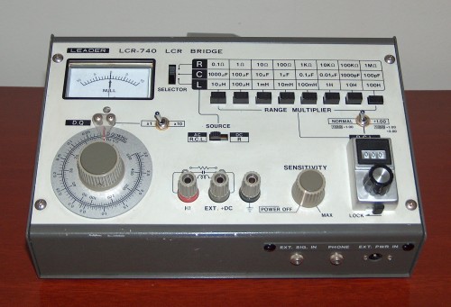
          I have this very same model, faithfully working since the late 70Žs:


          I think the caps shown are ceramics, value in pF is the printed number, and MN either shows voltage and tolerance or temperature coefficient or is plain brand indicator (Minnesota Capacitors anybody? )
          Click image for larger version

Name:	MysteryCaps.jpg
Views:	1
Size:	582.6 KB
ID:	846335
          Juan Manuel Fahey

          Comment


          • #20
            Originally posted by Tom Phillips View Post
            I'm wondering, during this whole thread, why all those parts were removed in the first place. I.e what troubleshooting pointed to them as "bad?"
            Me too! I would list bad semiconductors, electrolytics, then resistors as noise suspects in that order for a SS amp. Little caps like those would be last.
            Experience is something you get, just after you really needed it.

            Comment


            • #21
              Agree.
              Ceramic tubular capacitors, number is capacitance in pF, no need to stablish units, MN may be voltage and tolerance or temperature coefficient code, donŽt expect any mystery data.
              Or even plain Brand label.
              They should never have been pulled, shotgunning is a terrible repair technique and in any case they would never cause noise as described, which is way more possible coming from bad active components, in general ICs or transistors.
              Juan Manuel Fahey

              Comment


              • #22
                Originally posted by J M Fahey View Post
                Yes, they very much look like old style (say the 50`s, 60Žs) ceramic caps.
                If some factory was already set up to make them that way, they would keep doing so until dies or machines broke or wore off, they would be well amortized anyway.
                Any new production line would be set up to make them the modern way, of course.

                I read them as small value ceramics, visible value being from 33pF to 100pF, *very* hard to read on a multimeter since probably cable and test leads would already show more than 100pF.
                And if user is holding probes with his hands, forget about it.

                A proper LCR meter would have them attached to some terminals, no human hands nearby, and even so might show "parasitic" 10 to 50 pF, which would have to be substracted from displayed measurement

                I have this very same model, faithfully working since the late 70Žs:
                That LCR meter is a sweet unit, Fahey! I want one of those. I admit, I have a little bit of gear envy.
                (But how obnoxious is it the i look over and see the "range multiplier" switches and think "Ew! I would have to do it?" #spoiledbyautorange)
                If I have a 50% chance of guessing the right answer, I guess wrong 80% of the time.

                Comment


                • #23
                  I have one of these. current production, easy to find.


                  https://www.bkprecision.com/products...-with-esr.html
                  Attached Files
                  "Stand back, I'm holding a calculator." - chinrest

                  "I happen to have an original 1955 Stratocaster! The neck and body have been replaced with top quality Warmoth parts, I upgraded the hardware and put in custom, hand wound pickups. It's fabulous. There's nothing like that vintage tone or owning an original." - Chuck H

                  Comment


                  • #24
                    Originally posted by J M Fahey View Post
                    Agree.
                    Ceramic tubular capacitors, number is capacitance in pF, no need to stablish units, MN may be voltage and tolerance or temperature coefficient code, donŽt expect any mystery data.
                    Or even plain Brand label.
                    They should never have been pulled, shotgunning is a terrible repair technique and in any case they would never cause noise as described, which is way more possible coming from bad active components, in general ICs or transistors.
                    Hi JMF, point taken. I thought the shotgun replacing of the mystery capacitors would be a quick experiment before I go to replacing transistors and then IC's. I thought I was onto something when they wouldn't measure any capacitance with my multimeter (and a known .1uF cap measured fine). The transistors in this are unlabelled and I can't find a schematic, so I'm not sure how to approach that problem.

                    Comment


                    • #25
                      Originally posted by waspclothes View Post
                      Hi JMF, point taken. I thought the shotgun replacing of the mystery capacitors would be a quick experiment before I go to replacing transistors and then IC's...
                      The usual troubleshooting technique is to isolate the problem to a certain area of the circuit. Granted, that is hard to do if you don't have a schematic and are not familiar with the circuit in your amp. In post number 1 you said the equipment was a Carlsboro solid state amp. I suggest that we start by getting the complete model number and photos of the amp so the group can try to find a schematic.

                      Once we know more about the circuit then we can do troubleshooting to determining if various controls affect the noises. In addition, we can do various simple things to interrupt the signal path and/or dump the signal to ground with a temporary capacitor in certain places in the circuit and observe how that affects the noises. (Caution: Don't try this until you really understand the technique) Other things are thumping, poking & prodding, freeze spray, heat gun, pot, switch & connection cleaning and detailed visual inspection. The goal is to narrow down the section of the circuit where the noise is originating and all this comes before shotgun parts replacement.

                      Cheers,
                      Tom
                      Last edited by Tom Phillips; 09-04-2017, 05:00 AM.

                      Comment


                      • #26
                        Excellent advice and the way to go.

                        So far we know nothing, "Carlsbro SS amplifier" covers way too much, we need some focusing.
                        Post model, whatever is written on the backpanel, plus some pictures:
                        front and back panels, then pull chassis out and post preamp and poweramp pictures ... weŽll then ask for more

                        After we get some idea of what you have, weŽll suggest some tests.

                        I seem to have read no controls affect noise except Master Volume?

                        If so, you need to detect which is the last active section , based maybe on an Op Amp or perhaps a couple transistors, which feeds/drives that MV, I guess we wonŽt be far from the suspect.

                        Problem is Carlsbro was actually a very popular, widely sold and available British brand (I saw them all over the place in UK in Ž86, way more than Laney, Marshall or Vox, go figure) , but since "nobody famous" used them, they are ignored today.
                        HH was more famous, but also disappeared, was absorbed by Laney; another popular but obscure brand was Torque.

                        Sadly Music pages, IF they remember them somewhat, that applies only to Tube circuits, but never SS.
                        Juan Manuel Fahey

                        Comment


                        • #27
                          Originally posted by waspclothes View Post
                          I thought I was onto something when they wouldn't measure any capacitance with my multimeter (and a known .1uF cap measured fine).
                          This is what I was getting at. A .1uF is 100,000pF. You are trying to measure caps in the vicinity of what we think is 50pF. A lot of multi-meters with capacitance functions will not measure caps of such a low value.
                          I would guess that when you measure them, you get the same reading as when the probes are open and not touching anything.
                          If you were comparing to a known good 50pF cap, and the meter measured one but not the other, then you could suspect the cap.
                          Out of curiosity, what is the make and model of your meter?
                          Originally posted by Enzo
                          I have a sign in my shop that says, "Never think up reasons not to check something."


                          Comment


                          • #28
                            Originally posted by Pedro Vecino View Post
                            Ceramic tubular capacitors.
                            I remember those! Thin-walled, hollow, ceramic tubes, metallized on the inside and outside of the tube.

                            This thread is giving me flashbacks to my childhood. I started tinkering with electronics when I was about 8 years old, and saw a few of these ceramic tubular capacitors (pulled from dead electronics that was already old then) during my first few years in the hobby. I haven't seen any of them in a very long time, though.

                            -Gnobuddy

                            Comment


                            • #29
                              Originally posted by J M Fahey View Post
                              Agree.
                              Ceramic tubular capacitors, number is capacitance in pF, no need to stablish units, MN may be voltage and tolerance or temperature coefficient code, donŽt expect any mystery data.
                              Or even plain Brand label.
                              They should never have been pulled, shotgunning is a terrible repair technique and in any case they would never cause noise as described, which is way more possible coming from bad active components, in general ICs or transistors.
                              Just a quick update. I replaced all of the LM741 and CA741 op-amps and the noise is gone. Thanks everyone for their patience on this.

                              Comment


                              • #30
                                Glad to know
                                Juan Manuel Fahey

                                Comment

                                Working...
                                X