Ad Widget

Collapse

Announcement

Collapse
No announcement yet.

2 x 6SL7 + 6SN7

Collapse
X
 
  • Filter
  • Time
  • Show
Clear All
new posts

  • 2 x 6SL7 + 6SN7

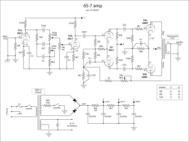
    I'm hoping for some criticism on this amp I built. It uses the two sections of a 6SN7 as a push-pull output stage, a la the AX84 October Studio. The preamp and PI tubes are old 6SL7s that I had on hand.
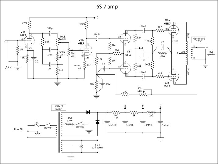
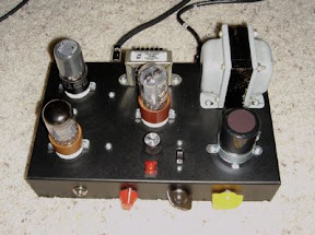


    The amp sounds good, although I can't decide if the breakup is as smooth (?) as I'd like.

    Is there anything obviously screwy about my design?

  • #2
    I wonder if you have too much filtering capacitance. You might try 16uF or 20uF at all positions or even lower in the preamp section.
    WARNING! Musical Instrument amplifiers contain lethal voltages and can retain them even when unplugged. Refer service to qualified personnel.
    REMEMBER: Everybody knows that smokin' ain't allowed in school !

    Comment


    • #3
      Originally posted by loudthud View Post
      I wonder if you have too much filtering capacitance. You might try 16uF or 20uF at all positions or even lower in the preamp section.
      Thanks for the suggestion. I changed the 33 & 22 to 22 & 10. Didn't make any noticeable difference.

      I'm wondering if larger resistors in that ladder would be better. The last two are dropping only a couple of volts each.

      Regardless, I'm starting to like the sound of it. I don't know what I'm complaining about.

      Comment


      • #4
        Originally posted by otto pärt View Post
        I'm wondering if larger resistors in that ladder would be better. The last two are dropping only a couple of volts each.
        Lowering the voltage to the preamp will give a little more compression. Do you get much B+ sag? The output stage is probably close to class A so I wouldn't expect much sag. It won't hurt to experiment.
        WARNING! Musical Instrument amplifiers contain lethal voltages and can retain them even when unplugged. Refer service to qualified personnel.
        REMEMBER: Everybody knows that smokin' ain't allowed in school !

        Comment


        • #5
          Have you tried it without NFB? I second the suggestion to drop the filter capacitors... given the current load here, you could put 10uF caps in each position and still have a very quiet amp. Is the 400-ohm resistor in the power supply just there to drop voltage?

          - Scott

          Comment


          • #6
            Originally posted by ThermionicScott View Post
            Have you tried it without NFB? I second the suggestion to drop the filter capacitors... given the current load here, you could put 10uF caps in each position and still have a very quiet amp. Is the 400-ohm resistor in the power supply just there to drop voltage?

            - Scott
            Thanks. I believe I will swap the big caps for smaller ones. Yes, the 400 ohm resistor is there just to drop voltage and, along with the resistor connected to the PT center tap, to create a little sag. Actually, I've bumped that resistor up to 800Ω/10W and the 1k resistor between A and B up to 4.7k. I think that's giving me a bit of compression. Anyway, I'm really liking the sound of it now.

            Also changed the NFB and tail resistances around a little bit and put an audio-taper pot there instead of linear. That works much better.

            Comment


            • #7
              If tube rectifier-like behavior is what you're after, try deleting that first filter cap. How much does the current draw in your amp vary when cranked?

              - Scott

              Comment


              • #8
                Originally posted by ThermionicScott View Post
                If tube rectifier-like behavior is what you're after, try deleting that first filter cap. How much does the current draw in your amp vary when cranked?

                - Scott
                Full tilt, about 40ma.

                I had convince myself that I was fairly happy with the sound of the amp after playing a Strat through it. Then I tried a Les Paul. Blech. So I added a bright cap to the volume control and removed the cathode bypass cap from the first stage. Much better! I'm thinking of adding a switch to bring that bypass cap in and out.

                Comment


                • #9
                  changing direction

                  It occurred to me that two cascaded preamp stages is complete overkill for this amp. What caused this revelation was the fact that humbucking pickups cause breakup with the volume control on 2!

                  So I've now replaced the first 6SN7 with a grid-leak biased 6SQ7 (an old metal RCA), and the volume control feeds straight into the LTP. It could use a little more gain, but it's good.

                  I might try a 6SJ7 (octal pentode).
                  Last edited by otto pärt; 12-20-2009, 01:14 AM.

                  Comment


                  • #10
                    Looking at the original schematic, if there is too much gain, what if you pulled the 470K plate resistors, and replaced them both with 100 K ? Would that not drop the gain down a bit ?

                    -g
                    ______________________________________
                    Gary Moore
                    Moore Amplifiication
                    mooreamps@hotmail.com

                    Comment


                    • #11
                      Originally posted by mooreamps View Post
                      Looking at the original schematic, if there is too much gain, what if you pulled the 470K plate resistors, and replaced them both with 100 K ? Would that not drop the gain down a bit ?

                      -g
                      Thanks. I did try that in the first stage, and it helped a little. But I've decided that a single preamp stage is the way to go.

                      I've added a couple of bells and whistles and declared it finished... until I decide to change something, of course, like replacing the 6SQ7 with a 6SJ7 pentode. It's a cool little amp and sounds great. The switches I added allow for variety of different sounds. Now I need to build a cabinet for it.
                      Attached Files

                      Comment


                      • #12
                        Hey Otto, do you remember the moonlight designed by Simcha Delft from about 2000? That had the same backend and an EF184 as the first tube.

                        Comment


                        • #13
                          Originally posted by sean k View Post
                          Hey Otto, do you remember the moonlight designed by Simcha Delft from about 2000? That had the same backend and an EF184 as the first tube.
                          No, that predates my obsession with this stuff. Thanks for the pointer!

                          BTW, teh Google shows me this: Adam's Amplifiers: Moonlight

                          Hmmm, the EF184 (6ej7) seems quite different from the 6sj7 I'm thinking of using...

                          Comment

                          Working...
                          X