Ad Widget

Collapse

Announcement

Collapse
No announcement yet.

Parallel Single Ended EL34 Amp Build

Collapse
X
 
  • Filter
  • Time
  • Show
Clear All
new posts

  • Parallel Single Ended EL34 Amp Build

    Hi every one, I'm new here but have been lurking for some time now.
    Lots of great info and knowledgeable people here I have to say!

    I'm looking for advise about this amp I've been building and I've been at for awhile because I keep changing it, LOL! I should have put it into a test box platform before putting into a chassis.

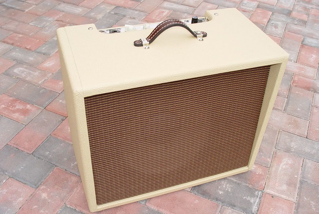
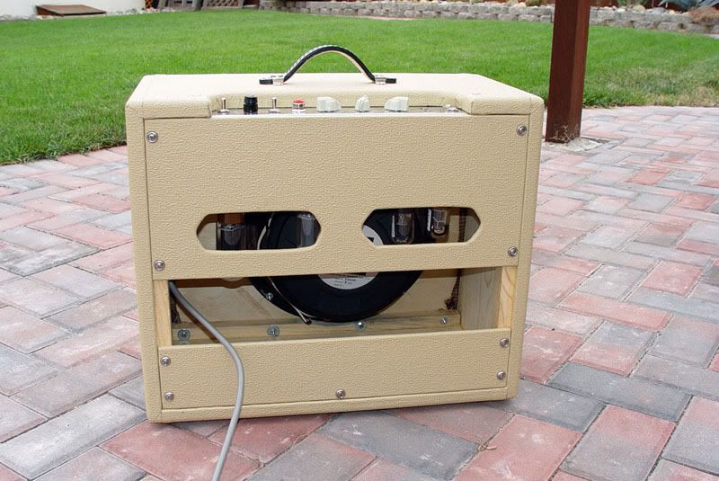
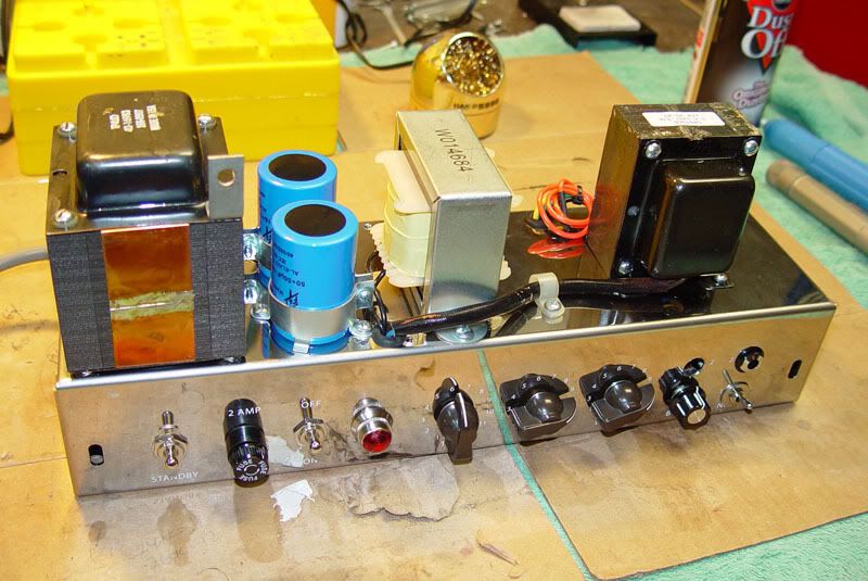
    It's a tweed deluxe 5C3 chassis from Weber in my self built 12" cabinet.
    In the vein of the old Gibson parallel 6v6 amps I built this with el34s, a 6SL7 preamp and all point to point wiring. The plate and cathode resistor values for the 6SL7 I got from the Angela super single ended schematic and the el34 values are fairly generic.

    The tone stack is a brown face Fender type and I adjusted the capacitor values to suit my tastes. I've wired in a tone stack by-pass, using a 2p3p switch, that puts it into a tweed style tone set up.
    The tone stack really sucks the power but it really screams in tweed mode.

    What I'm after here is:

    I think that the grid leak resistor for the el34s is incorrect. I got the 470k value by reading over some of the Valve Wizard's web page and that was for a single el34. The Valve Wizard -Single Ended

    And look over the schematic. I think I have it correct and any advice is much appreciated! The rest of the hard parts are shown on the schematic.

    Down the road I think I'm going to have to add another gain stage and a cathode follower stage to drive the tone stack.
    I really like this old Fender stack but it really sucks the gain. When I do this then maybe I can dump the Tweed switch.

    Thanks for any help and mucho appreciated.
    I put the schematic on a link because it's big, so old people like me can see it! http://i76.photobucket.com/albums/j7...one6-06-10.jpg

    Scott


  • #2
    Originally posted by maxwedge View Post
    I think that the grid leak resistor for the el34s is incorrect. I got the 470k value by reading over some of the Valve Wizard's web page and that was for a single el34. The Valve Wizard -Single Ended
    What are you wanting exactly? - more distortion?

    If so, its probably not a matter of 'incorrect' grid leak resistance. Quite possibly you possibly aren't driving the EL34 grids hard enough, but increasing teh grid leak resistance will have minimal effect on that. What you need is to get a bigger signal swing coming off the last driver stage, so maybe reconfiguring your pre-amp for more driver gain might help. (2CW of guesswork)
    Building a better world (one tube amp at a time)

    "I have never had to invoke a formula to fight oscillation in a guitar amp."- Enzo

    Comment


    • #3
      If you like the way the amp sounds and you just need more gain, why don't you just use a clean boost pedal?

      Comment


      • #4
        Originally posted by tubeswell View Post
        What are you wanting exactly? - more distortion?

        If so, its probably not a matter of 'incorrect' grid leak resistance. Quite possibly you possibly aren't driving the EL34 grids hard enough, but increasing teh grid leak resistance will have minimal effect on that. What you need is to get a bigger signal swing coming off the last driver stage, so maybe reconfiguring your pre-amp for more driver gain might help. (2CW of guesswork)
        Well, I suppose more distortion but not as much as a tweed circuit.
        The difference in volume between my tweed circuit and the tone stack circuit is: tone stack almost full up and tweed about 1/2. So yeah, I need to reconfigure the preamp like adding a gain stage. I don't think it'll need much to put it where I want it, I think.

        As far as the grid leak I was reading somewhere that said, in general terms, that when going from a single tube to two parallel tubes you should reduce the value to half of the original value. I know there's more tech involved and I know I should be using load lines to set this up but I don't quite understand them yet. I've been trying.

        I don't get what 2CW stands for? Thanks for the reply.

        Comment


        • #5
          Originally posted by olddawg View Post
          If you like the way the amp sounds and you just need more gain, why don't you just use a clean boost pedal?
          I have a OKKO Diablo but I'm really not into a boost pedal in front of this amp.
          I have other Fenders that work great with the boost pedal.
          Thanks

          Comment


          • #6
            If you look at the original 5C3 schematic you referenced, the preamp has grid leak bias. The 470K you are referencing is actually a load resistor for the PI circuit. 'Grid leak' is a bias method, and applies to preamps (there may be a few exceptions).
            Lift the ground connection on your tone stack for extra gain. You might not like the sound, but you will be able to see what more amplitude will do for your following stages. If you can get by with a single knob tone, or a bass/treble tweed tone circuit, you will have less EQ loss for more drive signal. My favorite tweed EQ is the one used on the Gibson GA-50.
            Black sheep, black sheep, you got some wool?
            Ya, I do man. My back is full.

            Comment


            • #7
              Originally posted by GibsonLover View Post
              If you look at the original 5C3 schematic you referenced, the preamp has grid leak bias. The 470K you are referencing is actually a load resistor for the PI circuit. 'Grid leak' is a bias method, and applies to preamps (there may be a few exceptions).
              Lift the ground connection on your tone stack for extra gain. You might not like the sound, but you will be able to see what more amplitude will do for your following stages. If you can get by with a single knob tone, or a bass/treble tweed tone circuit, you will have less EQ loss for more drive signal. My favorite tweed EQ is the one used on the Gibson GA-50.
              The only thing 5C3 here is the chassis I bought and the schematic I linked to is my own drawing of this amp I built. The 470k I'm talking about is the grid leak for the el34s.

              Are you talking about the ground on the bass pot where the 6.8k resistor is?
              Thanks, I'll take a look at the GA-50

              Comment


              • #8
                As you know by now, that tone stack is quite lossy. Using just two gain stages with a 6SL7 isn't going to drive those EL34's very hard. That's why you see such a big difference when you switch out the tone stack.

                What you might want to try instead of the tweed tone control is a variable bypass of the tone stack, a Raw control. You can do this by putting a large value pot wired as a variable in place of the mid resistor. Or, simply eliminate the switch SW1 and connect the tweed tone control up to the same point full time, then eliminate the .0047 cap to groun completely and replace the 470pf cap and connect the output of the pot to the grid of V2. Also get rid of Sw2, you want this pot always in circuit. You'll probably also want to use an audio pot not linear. You'll want to keep the .022 coupling cap between V1 plate and the Raw pot, to isolate it from DC. With this set up the pot fully counter clockwise will give you full tone stack performance, as you rotate the control clockwise the tone stack will slowly be bypassed, raising the gain and driving the EL34's harder, until it is fully engaged at which point the tone stack is fully bypassed. This control will give you better control over the change in gain, and will allow you to adjust how much Rawness you wantm from none at all (full tone stack) to full Raw (no tone stack) or any point in between.

                I've set up dozens of similar amps just like this, and it is very effective. The owners of those amps love it. Give it a try and see what you think.

                Comment


                • #9
                  Originally posted by hasserl View Post
                  As you know by now, that tone stack is quite lossy. Using just two gain stages with a 6SL7 isn't going to drive those EL34's very hard. That's why you see such a big difference when you switch out the tone stack.

                  What you might want to try instead of the tweed tone control is a variable bypass of the tone stack, a Raw control. You can do this by putting a large value pot wired as a variable in place of the mid resistor. Or, simply eliminate the switch SW1 and connect the tweed tone control up to the same point full time, then eliminate the .0047 cap to groun completely and replace the 470pf cap and connect the output of the pot to the grid of V2. Also get rid of Sw2, you want this pot always in circuit. You'll probably also want to use an audio pot not linear. You'll want to keep the .022 coupling cap between V1 plate and the Raw pot, to isolate it from DC. With this set up the pot fully counter clockwise will give you full tone stack performance, as you rotate the control clockwise the tone stack will slowly be bypassed, raising the gain and driving the EL34's harder, until it is fully engaged at which point the tone stack is fully bypassed. This control will give you better control over the change in gain, and will allow you to adjust how much Rawness you wantm from none at all (full tone stack) to full Raw (no tone stack) or any point in between.

                  I've set up dozens of similar amps just like this, and it is very effective. The owners of those amps love it. Give it a try and see what you think.
                  Thanks hasserl, I think this will be the way to go with out adding another stage. I think I was actually playing with something like this (the 2nd suggestion) at one point and switched it to a full by-pass. I go wire it up now.

                  Any opinion about my grid leak resistor value question for the el34s?

                  Thanks again,
                  Scott

                  Comment


                  • #10
                    Hi Scott

                    If the 470k is for 2 x EL34 in parallel, then yes you should go to 270K.

                    2CW = 2 Cents Worth
                    Building a better world (one tube amp at a time)

                    "I have never had to invoke a formula to fight oscillation in a guitar amp."- Enzo

                    Comment


                    • #11
                      Originally posted by tubeswell View Post
                      Hi Scott

                      If the 470k is for 2 x EL34 in parallel, then yes you should go to 270K.

                      2CW = 2 Cents Worth
                      LOL, ok 2 cents worth. Shoulda known. Thanks for that.

                      Comment


                      • #12
                        Originally posted by hasserl View Post
                        As you know by now, that tone stack is quite lossy. Using just two gain stages with a 6SL7 isn't going to drive those EL34's very hard. That's why you see such a big difference when you switch out the tone stack.

                        What you might want to try instead of the tweed tone control is a variable bypass of the tone stack, a Raw control. You can do this by putting a large value pot wired as a variable in place of the mid resistor. Or, simply eliminate the switch SW1 and connect the tweed tone control up to the same point full time, then eliminate the .0047 cap to groun completely and replace the 470pf cap and connect the output of the pot to the grid of V2. Also get rid of Sw2, you want this pot always in circuit. You'll probably also want to use an audio pot not linear. You'll want to keep the .022 coupling cap between V1 plate and the Raw pot, to isolate it from DC. With this set up the pot fully counter clockwise will give you full tone stack performance, as you rotate the control clockwise the tone stack will slowly be bypassed, raising the gain and driving the EL34's harder, until it is fully engaged at which point the tone stack is fully bypassed. This control will give you better control over the change in gain, and will allow you to adjust how much Rawness you wantm from none at all (full tone stack) to full Raw (no tone stack) or any point in between.

                        I've set up dozens of similar amps just like this, and it is very effective. The owners of those amps love it. Give it a try and see what you think.
                        I changed the schematic. Is this what you meant? Like this I'm not getting much tone control when the raw is turned down. May be I need to connect the raw to the right side of the volume pot? I'll go switch it and see what it's like.
                        Attached Files

                        Comment


                        • #13
                          Originally posted by maxwedge View Post
                          I changed the schematic. Is this what you meant? Like this I'm not getting much tone control when the raw is turned down. May be I need to connect the raw to the right side of the volume pot? I'll go switch it and see what it's like.
                          Yes, that should do it as long as CW is at the bottom of the pot (as drawn), so there is zero resistance at that point, and 1M resistance fully counter clockwise.

                          Comment


                          • #14
                            Originally posted by hasserl View Post
                            Yes, that should do it as long as CW is at the bottom of the pot (as drawn), so there is zero resistance at that point, and 1M resistance fully counter clockwise.
                            That's how I had it but I changed it because the bass and treble had almost no effect even with the raw pot at 1M. So I switched the raw output to the right terminal of the volume pot. This seems to work much better and it now has full function of the bass and treble. It seems to work well if I use both the raw and volume to set my max distortion and volume and then back it down and use only the volume.

                            Really appreciate you input
                            New schematic
                            Attached Files

                            Comment


                            • #15
                              Hi Scott

                              re: your last schematic - I see you have a 47k NFB resistor. Try upping that to say 100k (or even 220k) that will get a raw-er sound. Or try disconnecting it altogether.

                              Another simple thing you could try on that schematic is up that second plate resistor to 220k and drop the cathode resistor to 1k5.

                              Another 2CW
                              Building a better world (one tube amp at a time)

                              "I have never had to invoke a formula to fight oscillation in a guitar amp."- Enzo

                              Comment

                              Working...
                              X