Ad Widget

Collapse

Announcement

Collapse
No announcement yet.

Resistor voltage ratings

Collapse
X
 
  • Filter
  • Time
  • Show
Clear All
new posts

  • Resistor voltage ratings

    I'm now shopping for resistors and have come up with a question :

    Am I correct in believing that the "maximum working voltage" specification
    for a resistor refers to the voltage drop across it, and not the actual
    voltage applied with respect to ground ? I ask this because most 1/2 watt
    resistors are rated at 300-350v (or less) and resistors in amps can have
    voltages a lot higher than that applied. (I did find some military resistors
    at Mousers that could handle 500v but you have to buy a minumum of 200
    pieces.)

    I don't see any places in my schematics where the voltage drop across a
    single resistor would be over 300V.

  • #2
    Paul,

    Did you post about this recently at the old Ampage site? Maybe it was someone else... at any rate, the voltage rating is across the resistor, not to ground (unless one end of the resistor is grounded, of course). A 350V resistor could be suspended in mid air - nowhere near a ground - and have 3,500 volts applied across it, and it would flash right over.

    Do you have some resistors that are in intimate contact with the chassis or some other grounded component, and you're worried they'll arc?

    Here's a link to Digi-Key's metal film resistors - minimum quantity 5, the 2W are rated for 500V and the 3W for 750V, and they're small - let's see if the 'Insert Picture' button actually works:


    If not, the link is http://dkc3.digikey.com/PDF/T062/1294.pdf


    Ray

    Comment


    • #3
      Originally posted by Ray Ivers
      Did you post about this recently at the old Ampage site?
      Not me. I've mostly moved here now. Lots of room
      Do you have some resistors that are in intimate contact with the chassis
      or some other grounded component, and you're worried they'll arc?
      No, I'm just getting ready to place a couple of orders to stock
      up on amp parts and came across the maximum voltage specification
      which I'd never thought about before (I have some limited experience
      in solid state and digital stuff - voltage was never an issue.)

      Just wanted to make sure before I bought a few hundred resistors.

      Thanks.

      Comment


      • #4
        Yup, you've got it pretty much correct. The voltage rating is ACROSS the resistor. By the way it works the same way for coupling capacitors! I think Enzo brought this up in passing over on the old Ampage but it's worth repeating....

        The way they manufacture metal and carbon films is that they cut a spiral in a coating of metal or carbon film whch creates something of a faux wirewound resistor. And at higher voltages these siprals can arc over and causes the resistor to fail.

        Carbon comps are a little different in that they use a slurry of carbon based material that is formed into a resistive paste and compressed to make the body of the resisor. There's really nothing to arc over here which is why you generally have a higher rating on carbon comp's than films. However these fail as a result of the voltage potential "punching through" this material in a similar way that voltage can punch through insulation on wires. Also this material can dry up over time and get overly brittle and develop microscopic fractures in the body. This causes a momentary discontinuity and is why older comps tend to snap, crackle, and pop.

        As an aside, if your margins are tight you really should account for the AC component as well. For instance, if you have a resistor hanging off a 300 volt node and it has a 100 volt AC signal riding on it, the AC is going to increase and decreas the value of that 300 volt node by about 140v at the peaks and troughs. So in this particular case, you're fine with a 350v rated resistor in steady state but during operation the resistor would fail! In most cases it's not a problem but it's still something to keep in mind when you're selecting components.


        -Carl

        Comment


        • #5
          Resistors - High voltage rating

          I have been working with a high voltage application - electric fence testing. Voltages reach 15kV in the area I am working in.

          Ordinary resistors are rated miles below this so what do you do? I looked up high voltage resistors and found that 10kV resistors are commonly available for TV focus controls. You can even buy pots for 10kV. For me, I used two resistors of half the required value - in series.

          Look up "Focus Resistors" as TV repair suppliers carry them. In Sydney, this is Wes in Ashfield, NSW. Values start at 100k ohms and go up to 10M ohms and all are rated at 1 watt.

          I need 1m/A so 1W is a suitable rating for me. I also bought 2 HV pots, good for 10kV. These were 10M, 15M and 20M ohms. Wattage unknown but probably 1W also. Their packaging implies that. This is a guess however, and I cannot find specs to support this view.

          Philips make these resistors. Some years ago I was able to source some 1000Meg ohm resistors - again Philips. They did not use a colour code (damnit, couldn't you surprise some people with brown-black-grey resistor code??). Most would think they had it wrong! The value was printed on the side, 20% rating and built on a glass substrate. To me, Philips are a tremendous supplier, especially of oddball components. Everything mentioned above was Philips made.

          Resistors in microwave ovens just might support voltages over 1kV - not sure. I wouldn't bet on it while I can guarantee the TV focus resistors - I am holding them right now - bought them this morning.

          Cost was 90c per resistor, or 81c for 10+. The pots were $4.15 each. These are good prices for such rare or unusual components.

          Finally, they are 4 band resistors. Three value, and the tolerance. The tolerance band was yellow (not gold). No web site I have seen lists yellow as a tolerance of any sort. How did I know it was yellow and not gold (some colours are fairly close)? One value I bought was 470k, so I had a sample of yellow already. Guys, it was the same - yellow for tolerance. Who knows!!

          The resistors were bigger than the newer style of 1W resistors which are quite small compared to resistors of 30 years ago. Hardly surprising when you consider physical size is necessary to avoid arcing. They had a light sky blue body.

          Hope this helps someone (Paul P - though your enquiry was some time ago). I doubt you will find many conventional resistors with a 10kV rating so easily. Wes, the supplier, is a huge outlet for the radio and TV trade. You wil need one of these places as opposed to general electronics stores or hobbyist ones.

          If you want more help, email me at brett2010@ymail.com - especially if you are in Australia.

          Comment


          • #6
            Originally posted by brett2010 View Post
            Philips make these resistors. Some years ago I was able to source some 1000Meg ohm resistors - again Philips. .
            1000MOhms! If I am not mistaken isn't this is equal to about 1cm of open air? (10^10 ohms/m)


            Caddock is the HV resistor Mfg. I am familiar with, here is a ~15MOhm version...though only 2kv
            Caddock 14.6M 2KV .8 watt Resistor-The Electronic Goldmine
            fairly cheap while 20kV 1M (8w!) are $65 at Surplus Sales of Nebraska

            Beman makes (made?) some freaky high voltage resistors...200G Ohms?


            Just read a Tesla Biography...and will avoid too many kvs...


            Most KOA Speer MF1 series resistors are rated at 500v for 1/4w, and the 1/2w are 700v

            Comment


            • #7
              1000M Resistors

              Originally posted by tedmich View Post
              1000MOhms! If I am not mistaken isn't this is equal to about 1cm of open air? (10^10 ohms/m)

              REPLY: Yes, you are possibly right. However, it is a CALIBRATED cm of air. I bought 10 for a science experiment at school. The concept was to see if current stopped flowing at a certain point. The exact definition of current escapes me right now, but involves X number of electons flowing in a conductor per second. The experiment was to reduce this to 1 electron per second and then reduce the current further, with a lowish value of resistor, and see if EITHER (1) Current stopped completely =OR= (2) reduced to 1 eletron per 2 seconds (or whatever).

              My teacher, knowing the difficulties I would face allowed me to proceed using my own ideas (with the odd bit of help). I never got to prove or disprove this idea, but the idea intrigued the judges and I was awarded a decent prize as it was considered an advanced concept for a 12 or 13 year old kid. And, I needed calibration. Mostly this was in the power supply using a series of 'divide by 100 voltage dividers', but also, in final stages, I needed accuracy in the resistor chain. See the photo - the centre resistor is 1000M ohms and can be seen in the pic (pardon my amateur photography - yours is far superior).

              Just as you have never heard of Philips, I have not personally come across Caddock.

              Also, the lower resistor in the pic is 270k ohms, showing clearly the two yellow bands. This is the resistor I maintain can support a voltage across it of 10kV. At the top is the pot of similar rating.

              To help you, or anyone else doubting my data; or thinking I have made an error, the part number of the resistor is 1FCR270k. The 1 is the wattage, FCR=Focus, and 270k is, guess what - the value in ohms. You will find 1FCR330k, 390k, 1M, etc, up to 10M.

              The pot part number is simply FCP15M, being FOCUS Pot (abbreviated down), and the value at the end, here it is 15M ohms.

              All the data and assumptions come from a technical catalog so if I am mistaken, it is in good faith. I take your point that the resistor you show is 2kV yet much longer. I have no explanation except the wattage might be far higher than 1W.

              Look at the WES (Wagner Electronic Supplies) site. I have not checked but another huge component supplier is Farnell (or Farnell at Home) and you might try them too. Finally, Philips is the source of the 1000M device. Try their site to confirm these things exist. I bought these while at school, which was nearly 40 years ago, and I doubt these were ever a fast moving item. I recall they were moderately expensive compared to ordinary resistors.

              The detail given, including part numbers is so that you, or anyone else can search for them, using the part numbers as search keys. You are not the first person comparing 1000M ohms as equivalent to an air gap. Click on the pic for more detail.

              And finally, I am stunned by the prices you quote - hell, I have seen microwave ovens for that price - if that is where they came from. And 200G? Wow. I don't doubt you but where on earth would one use it? I thought 1000M (1G ohm) was huge! It probably has some obscure use, like a specialist circuit in a particle accelerator ... maybe? I bet they are not fast moving items either!

              Also, I would not personally trust resistor voltage ratings and wattages. They may be an industry standard, but I have seen some cheap Asian components (mainly semiconductors) that just do not meet the specs of American or European manufacturers. Sure, you save half a cent, but is it really worth it.

              What was the name of the Tesla bio/autobio you read? These can be fascinating, and as there is more than one, I'd take notice of a recommendation.
              Attached Files
              Last edited by tboy; 10-10-2009, 11:40 PM. Reason: fixed quote tag

              Comment


              • #8
                It was Marget Cheney's "A Man Out of Time" which is almost 30yrs old, next will be her newer book "Master of Lightning"


                Tesla was a supreme oddity!

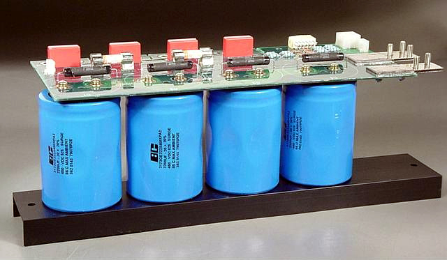
                On (moderately high) HV, Apexjr has a nice capacitor bank for sale: 3300uf 1.8kv only $35


                ~ 5300 Joules!

                Comment


                • #9
                  To make a high voltage resistor, just connect a bunch of ordinary ones in series. This has always worked for me. For really high voltage, start with the Vishay VR37 resistors, they can take a good few kV each to start with and are available in really high values. I bought about a hundred 10M ones years ago, and still have plenty left.

                  When making precision high voltage measurements, you have to be really careful about corona losses, which can ruin your accuracy. Precision HV AC measurements are even harder because of stray capacitances.

                  Tesla coils used to be my other hobby: my personal best spark was 6ft 9ins, with a coil that produced about 4kW of power, at 500kV and 66kHz. I don't have "Man Out Of Time", but I do have the Colorado Springs Notes, and "Experiments with alternate currents of high potential and frequency".
                  "Enzo, I see that you replied parasitic oscillations. Is that a hypothesis? Or is that your amazing metal band I should check out?"

                  Comment


                  • #10
                    Originally posted by Steve Conner View Post

                    Tesla coils used to be my other hobby: my personal best spark was 6ft 9ins, with a coil that produced about 4kW of power, at 500kV and 66kHz. I don't have "Man Out Of Time", but I do have the Colorado Springs Notes, and "Experiments with alternate currents of high potential and frequency".
                    One hopes breathing all that ozone didn't make Tesla the oddball he was, you don't have an inordinate fondness for pigeons do you Steve?

                    Your Tesla guitar amp demo remains one of my favorite youtubes...I can't believe Buckethead didn't want one...

                    Comment

                    Working...
                    X