Ad Widget

Collapse

Announcement

Collapse
No announcement yet.

Reverb unit scratch build questions

Collapse
X
 
  • Filter
  • Time
  • Show
Clear All
new posts

  • Reverb unit scratch build questions

    Hello all. I'm fairly well a newb to amp building and circuitry. I have plenty of experience with A/C power but DC and audio circuits I am pretty green. I have built one amp in the past, a 5e3, and it came out pretty well with only simple obvious bugs to sort through after its completion. I undertand a little of the basics of what goes on electronically but I am by and large on the dark side of the learning curve in this department. some times I could use a little light

    Anyhow, I am on the verge of ordering parts for a 6G15 reverb unit build and I have a couple questions.

    First, is it worth putting extra money into the pots? I don't mind spending the extra money for good ones if I am going to be able to enjoy a noticable advantage. Usually I would select CTS or something similar, not the cheapest but certainly not the most expensive. I looked at Allessandro and Precision Electronics pots at AES. And what about audio vs linear taper? They didn't have many values to choose from in the linear taper section, would I want to use audio T?

    Secondly, For caps I have selected Illinois filter caps, Sprague Atoms for the 25uf & 250uf positions and stock AES metal film caps for all other positions. Are there any particular cap positions that I would really benefit tone-wise from spending more money? I thought about finding some NOS and/or used OEM caps but most of them are sold by random ebayers and there's no telling what they will say in their ads to sell them. And does overspec-ing the voltage rating ever hurt things sound-wise?

    And lastly, has anyone used any transformers from triode electronics? Good experiences? They've got a nicely priced, convenient 3 pack set for this particular build. I was inclined to look for old/vintage transformers to use but that seems like a long and tedious process to find them.

    Oh yeah, almost forgot. What are the pros and cons of installing a prebuilt bridge recto or just making one out of some diodes?


    Thanks for your time.
    ~Semi-No0b Hobbyist~

  • #2
    Originally posted by mort View Post
    First, is it worth putting extra money into the pots? I don't mind spending the extra money for good ones if I am going to be able to enjoy a noticable advantage. Usually I would select CTS or something similar, not the cheapest but certainly not the most expensive.
    Well - pots are pots.

    Originally posted by mort View Post
    I looked at Allessandro and Precision Electronics pots at AES. And what about audio vs linear taper? They didn't have many values to choose from in the linear taper section, would I want to use audio T?
    Just use what's on the schematic

    Originally posted by mort View Post
    Secondly, For caps I have selected Illinois filter caps, Sprague Atoms for the 25uf & 250uf positions and stock AES metal film caps for all other positions. Are there any particular cap positions that I would really benefit tone-wise from spending more money? I thought about finding some NOS and/or used OEM caps but most of them are sold by random ebayers and there's no telling what they will say in their ads to sell them. And does overspec-ing the voltage rating ever hurt things sound-wise?
    Nah - just use film caps and silver micas for the signal path and e-caps for the bypass caps and filter caps. I wouldn't use cap-cans tho

    Originally posted by mort View Post
    And lastly, has anyone used any transformers from triode electronics? Good experiences? They've got a nicely priced, convenient 3 pack set for this particular build. I was inclined to look for old/vintage transformers to use but that seems like a long and tedious process to find them.
    Can't speak for the triode transformers but their chokes are good. Choke 40mA 4H Fender Deluxe / Champ is all you need

    Make sure the trannies are preferably well-shielded (preferably with end-bells). Stray EMI coupling into the pan transducers can be an issue in those confined space of that little cabinet. Getting a low SN ratio is all important with these units, because they sit in front of another amp. In that regard grounding is also important. I used R.G. Keen's grounding method (attached) in my one with very low hum results

    I reckon 5K Pr Z on the RT is best for these, because 8k just leaves you with untold trashy distortion, which is not what you want in a reverb unit.

    Originally posted by mort View Post
    Oh yeah, almost forgot. What are the pros and cons of installing a prebuilt bridge recto or just making one out of some diodes?
    You can use a 220-0-220 to 240-0-240 PT and FW SS rectification with 47uF filter caps, and get the ballpark voltage for this unit
    Attached Files
    Building a better world (one tube amp at a time)

    "I have never had to invoke a formula to fight oscillation in a guitar amp."- Enzo

    Comment


    • #3
      Thanks for the response.

      Here is the tranny bundle I am looking at: 6G15 Add On Reverb Unit Transformer Bundle w/ Choke - eBay (item 200458934110 end time Oct-04-10 09:03:17 PDT)

      and the reverb pan(but not from this site): http://www.guitarpartssite.com/ACCUT...9ab2c1b-ce.htm

      Any good reason not to use this transformer bundle? Again, I don't mind spending a little extra to get it right the first time.
      ~Semi-No0b Hobbyist~

      Comment


      • #4
        Originally posted by mort View Post
        Thanks for the response.

        Here is the tranny bundle I am looking at: 6G15 Add On Reverb Unit Transformer Bundle w/ Choke - eBay (item 200458934110 end time Oct-04-10 09:03:17 PDT)

        and the reverb pan(but not from this site): http://www.guitarpartssite.com/ACCUT...9ab2c1b-ce.htm

        Any good reason not to use this transformer bundle?
        That PT will give you the 'traditional' 6G15 PT, which with traditional 6G15 Half Wave rectification, is designed to replicate the 6g15. The reason I suggest using a PT that supports FW SS rectifier is you theoretically get better filtering from a FW rectifier (because the time gap between maximum voltage pulses in a FW rectifier is 1/2 what it is with a Half Wave rectifier, so a FW rectifier reduces the work that the filter has to do to smooth out the ripple). Remember that anything you can do to reduce the risk of a high noise:signal ratio at the output of these units is beneficial. 220-0-220 to 240-0-240 puts you in the ballpark for a 310-340VDC B+, which is ideal for this circuit. The pan just needs to be a pan with an 8R input transducer and whatever 170R + impedance for the output transducer
        Building a better world (one tube amp at a time)

        "I have never had to invoke a formula to fight oscillation in a guitar amp."- Enzo

        Comment


        • #5
          THIS followed by THIS made with THESE then?

          I'm not sure I understand the 220-0-220... is that for non American voltage? I have yet to wrap my head around the specs for these types of transformers. Please forgive my no0bness.
          ~Semi-No0b Hobbyist~

          Comment


          • #6
            I own a '60s vintage 6G15 reverb and have always loved the sound. I decided to build a clone a while ago. The project turned out very well. I made a few "improvements" such as employing a full wave bridge rectifier. The original unit has a two spring tank. I also chose a three spring accutronics unit. The tank in the original mounts with the open face towards the front of the cabinet. This allows for a lever mechanism that is used to clamp the tank down for transport. Like you, I went with a tank that mounts open face down. This required some modification of where components were mounted on the chassis. All of my transformers and the filter cap tank are on the forward facing side of the chassis. This was necessary to allow clearance for the reverb tank. I had no means of bending heavy gauge sheet metal for a chassis, so I used two sections of 1/8" thick aluminum angle iron. It provided a very strong chassis. True to the original I made my clone with PTP wiring on eyelet board.

            I have to say that while I tried not to make any modifications other than the rectifier and tank mentioned above, the clone sounds different than the original. It sounds good, but different and I like the original better (probably due to 40+ years of hearing it!). I did swap the tanks and that did not change the sound much if at all.

            I can provide gut shots and dimensions of the original if you would like to make your reverb as close to the original as possible.

            Here is some pictures of my two units. I am afraid that the build was done in the days before I got a little more concerned about lead dress. The connections to the tubes are not all that pretty! I should probably go back and tidy them up.


            Comment


            • #7
              Originally posted by Kazooman View Post
              I own a '60s vintage 6G15 reverb and have always loved the sound. I decided to build a clone a while ago. The project turned out very well. I made a few "improvements" such as employing a full wave bridge rectifier. The original unit has a two spring tank. I also chose a three spring accutronics unit. The tank in the original mounts with the open face towards the front of the cabinet. This allows for a lever mechanism that is used to clamp the tank down for transport. Like you, I went with a tank that mounts open face down. This required some modification of where components were mounted on the chassis. All of my transformers and the filter cap tank are on the forward facing side of the chassis. This was necessary to allow clearance for the reverb tank. I had no means of bending heavy gauge sheet metal for a chassis, so I used two sections of 1/8" thick aluminum angle iron. It provided a very strong chassis. True to the original I made my clone with PTP wiring on eyelet board.

              I have to say that while I tried not to make any modifications other than the rectifier and tank mentioned above, the clone sounds different than the original. It sounds good, but different and I like the original better (probably due to 40+ years of hearing it!). I did swap the tanks and that did not change the sound much if at all.

              I can provide gut shots and dimensions of the original if you would like to make your reverb as close to the original as possible.

              Here is some pictures of my two units. I am afraid that the build was done in the days before I got a little more concerned about lead dress. The connections to the tubes are not all that pretty! I should probably go back and tidy them up.
              That looks great! Did you mount the filter caps on the back? I'm planning on squeezing them in between the PT and main board. Also, what transformers and rectifier did you use?

              And I don't think they even make a side mounting reverb pan anymore, I can't find one anywhere.

              And I can understand about rushing through the wiring. I did that on my first build and it looked awful in there. Later I did go back and removed every bit of wiring and redid it. Looks much better now
              ~Semi-No0b Hobbyist~

              Comment


              • #8
                Here's how I plan to layout the rectifier and filters caps:

                The recto (either premade or self built should be able to fit on the left side of the eyelet board here...


                And then this board will mount between the main board and the PT aznd holder the filter caps:


                Can the recto be that close to the signal circuit or should I keep it as far away as possible?
                ~Semi-No0b Hobbyist~

                Comment


                • #9
                  Originally posted by mort View Post
                  THIS followed by THIS made with THESE then?
                  the 260-0 with a FW bridge will get ~370 B+, which will work fine (and probably be quite chimey, which you may or may not like). If you want 6G15 schematic spec voltage, then use a PT rated at about 210-0 or 230-0

                  Originally posted by mort View Post
                  I'm not sure I understand the 220-0-220... is that for non American voltage? I have yet to wrap my head around the specs for these types of transformers. Please forgive my no0bness.
                  220-0-220 (or 240-0-240 etc) is a spec for a high-tension secondary winding with a centre tap, which you could use with a Full Wave SS rectifier like in this schematic (never mind the euro voltage on the primary side - you want a US voltage PT). It is just a different way of getting the same result as using the above PT with a FW bridge.
                  Attached Files
                  Building a better world (one tube amp at a time)

                  "I have never had to invoke a formula to fight oscillation in a guitar amp."- Enzo

                  Comment


                  • #10
                    This is taxing my memory a bit. I decided to use the power supply design that is employed in the '63 Fender Reverb Reissue Series. I have an eight page service manual for that with the schematic and layout as well as a detailed parts list. The remainder of my unit is just as in the original. The power transformer is mounted at one end (near the cord). In the original the PT is inside the chassis. Mine wouldn't fit and I could not have it hanging down due to the reverb tank so it is on the back of the chassis. Next is the choke and then the reverb transformer. The filter cap tank is in line with the main circuit board. In my picture the rectifier bridge is on a small eyelet board that is mounted on the side wall of the chassis, just across from the pilot lamp. Between the rectifier board and the power cord you can just see one of two big diodes that are in the connection to the mains ground.

                    I can't remember where I got my transformers and choke. I do recall researching suitable parts based on the original Fender part numbers. At the time I was buying a lot from MOJO and Angela, so that may be where I got them. The reverb transformer part number is P-TF22921 and the choke is P-CF22707. The power transformer is a Hammond 269EX.
                    Attached Files

                    Comment


                    • #11
                      Well I went ahead and placed my orders today. Parts are split up between Mojo and Antique Electronic Supply and the xformers are on order from Weber, $68 shipped for the 3 of 'em... not bad at all.

                      I decided to use CTS for the 250k pots and Alpha for the 50k. The reverb tank is the type 4, 2 spring 8 ohm input accutronics. Tubes are coming from a guy on Ebay, old, tested tubes that are pretty inexpensive.

                      The enclosure is going to be the real challenge I think. I ordered planks of curly maple and I'm going for a natural grain look with dovetail joints, etc, etc. AND I AM NOT A WOODWORKER lol. If I can find someone to do it for me I will pay them... otherwise I'll be risking some expensive lumber to my mistakes
                      ~Semi-No0b Hobbyist~

                      Comment


                      • #12
                        Well, as fate would have it, I just happen to be a woodworker too! Actually, I know a quite a bit more about woodworking than I do about electronics. Let me know how I can help.


                        Peruvian walnut chest with purple heart trim and claro walnut top.

                        Just a few caveats: high end working with wood requires a whole lot of tools from large machinery, through quality hand held power tools, down to the smallest pieces. It costs a WHOLE LOT MORE than hobby level electronics. A single carbide router bit can cost more than all of the components for a good effects pedal. The wood for the blanket chest shown ran about $500. ALL of your major or even minor mistakes show on the surface. Very satisfying when you get it right and horribly frustrating when things don't go right.

                        There is a lot to be said for a good tolex covered enclosure. To do it right requires making sound finger or dovetail joints, routing smooth curves on the edges, and then a good tolex job. Going for a natural wood finish takes all of this to another level. Good fun in its own right, but don't let it put you off from building a great reverb. Choose your battles in the appropriate arenas where you are comfortable with the challenge.

                        Comment


                        • #13
                          You wanna just build it for me!! lol

                          That's a nice looking chest man, very nice indeed. I was amazed at how expensive the material gets for this sort of thing. I felt like I did very well to get 8.5 board feet of curly maple for around $55 shipped. At my local woodcraft store it would have been well over $100 for the same material.

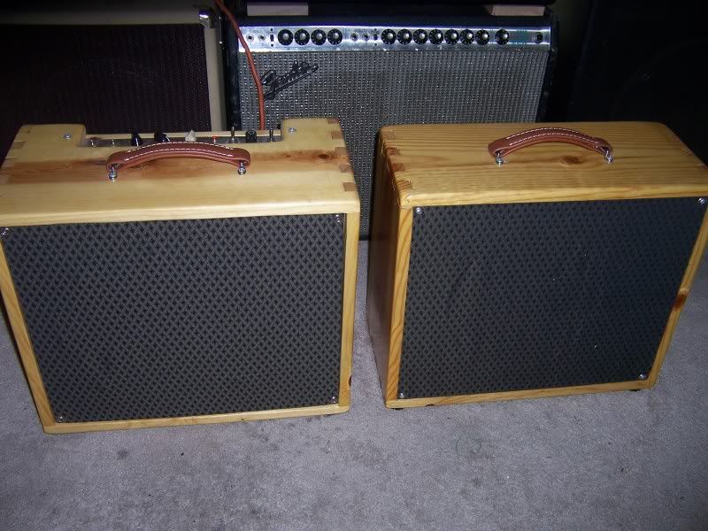
                          My first attempt at finger jointing was luckily on an amp that I *wanted* to look kinda rustic. I just used pine and threw some poly over the top of it. It came out pretty close to my target idea so I was pleased. I learned very quickly that to have a nice smooth joint that it would require alot of tools that I can't justify buying as I do very little woodworking type stuff. And a high powered belt sander helps

                          Here's a photo of my results as an absolute no0b:

                          ~Semi-No0b Hobbyist~

                          Comment


                          • #14
                            That looks great to me! Good joinery takes patience, practice, and good tools. I am never at a loss for kindling for my fireplace. I often get to start the fire with some nice pieces of cherry or walnut with dovetail failures on the ends It is a good idea to have some pieces of less expensive wood with identical dimensions to use for practice and for adjusting the tools prior to investing the good stuff. Good luck!

                            Comment


                            • #15
                              FWIW I'm a clod-fotted wood and metal worker too - Here's how mine started. I used a mixture of pine and 2nd-hand draw ends. Chassis is the usual hand bent thang with muh home-made board. Mistakes covered in gingham. Works like a charm

                              I think even if you are rudimentary at craftwork, you can get okay results with a few carefully chosen tools. Tool up gradually. I invested in a hand-router and some round-over bits and a hole saw after my first amp. (I already had a orbital sander, jig saw, drill, and wood plane plus the usual hammers etc)
                              Attached Files
                              Building a better world (one tube amp at a time)

                              "I have never had to invoke a formula to fight oscillation in a guitar amp."- Enzo

                              Comment

                              Working...
                              X