Ad Widget

Collapse

Announcement

Collapse
No announcement yet.

Fender Dlx Rev build- last Q b4 fire-up.

Collapse
X
 
  • Filter
  • Time
  • Show
Clear All
new posts

  • #91
    Sea Chief - Now Hear This...

    Even if the resistors you received are indeed 1/2 Watt parts, 1 Ohm 1/2 Watt resistors are perfectly acceptable as bias current sense resistors for a Deluxe Reverb Clone. Some people would even argue that 1/2 Watters or even 1/4 Watters would be more desirable than 1 Watt in that application because they would provide some fusing protection. You are good to go.

    Regards,
    Tom

    Comment


    • #92
      I dunno Tom. I have a drawer full of 1R/1W that I use as current sense resistors in builds. Sometimes when setting the bias on an amp I just tack one in for both tubes. I've popped more than one on amps with two big bottles that way. Never during biasing, but when I start crank testing the amp. Tube amps bump and spike like crazy when clipping and I'm sure this is what pops the resistor. This would imply though that one half watt resistor per side should work for a pair of small bottles but I'd like a little more over rate just to avoid getting shut down at a gig.
      "Take two placebos, works twice as well." Enzo

      "Now get off my lawn with your silicooties and boom-chucka speakers and computers masquerading as amplifiers" Justin Thomas

      "If you're not interested in opinions and the experience of others, why even start a thread?
      You can't just expect consent." Helmholtz

      Comment


      • #93
        Originally posted by Chuck H View Post
        ...I have a drawer full of 1R/1W that I use as current sense resistors in builds. Sometimes when setting the bias on an amp I just tack one in for both tubes. I've popped more than one on amps with two big bottles that way. Never during biasing, but when I start crank testing the amp...
        That's perplexing Chuck. Consider that to dissipate 1W in a 1 Ohm resistor there must be 1 Amp flowing through the resistor. Even then the resistor may not "pop." Also consider that a 100W Marshall amp uses a 1A fast blow fuse in the B+ line and there is no reported problem with nuisance fuse blowing. That fuse only blows when there is a problem such as a shorted power tube. The 1 Amp fuse survives all the bumps and spikes when the amp is clipping. If the fuse survives then the 1 Ohm 1W resistor should survive too. Therefore, the logical conclusion is that there is something else going on to cause your resistors to "POP" under the operating conditions that you describe. Maybe a bad batch of resistors?

        There are some other factors such as the type of resistor. However, I'm still surprised that you would be popping 1 Ohm 1 Watt resistors even if there was only 1 installed in a two bottle amp.

        Comment


        • #94
          Originally posted by Tom Phillips View Post
          That's perplexing Chuck. Consider that to dissipate 1W in a 1 Ohm resistor there must be 1 Amp flowing through the resistor. Even then the resistor may not "pop." Also consider that a 100W Marshall amp uses a 1A fast blow fuse in the B+ line and there is no reported problem with nuisance fuse blowing. That fuse only blows when there is a problem such as a shorted power tube. The 1 Amp fuse survives all the bumps and spikes when the amp is clipping. If the fuse survives then the 1 Ohm 1W resistor should survive too. Therefore, the logical conclusion is that there is something else going on to cause your resistors to "POP" under the operating conditions that you describe. Maybe a bad batch of resistors?

          There are some other factors such as the type of resistor. However, I'm still surprised that you would be popping 1 Ohm 1 Watt resistors even if there was only 1 installed in a two bottle amp.
          Well don't think it doesn't surprise me every time it happens. I do know that I commonly see reports of peaks over 200W for 50W rated tube amps under clipping conditions. That's getting to over half a watt across a 1R cathode resistor right there. So who knows what sort of spikes are happening fast enough that normal bench jockey equipment doesn't read it? All the guys that say watts are watts and that SS amps rated at X watts are just as powerful as old school design tube amps rated at X watts are just wrong. It isn't that SS amps aren't truly up to the watts. It's more that the tube amps are greater than their rating under certain conditions. My point is just that I'm not equipped or inclined to challenge your logic with math because the documented evidence isn't available. I'm just saying that it happens. I'll also say that no 100W Marshall of mine is going on stage with a 1A fast blow mains fuse Keeping in mind I'm in a 120V mains country.
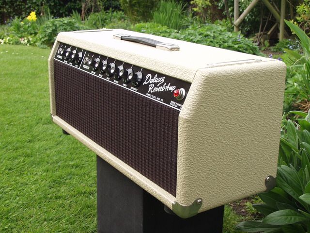
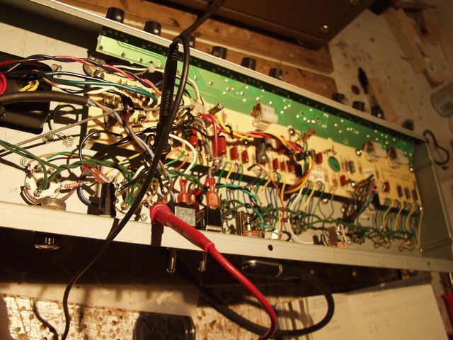
          To be fair, I hadn't considered a marginal batch of resistors. But I am now.
          "Take two placebos, works twice as well." Enzo

          "Now get off my lawn with your silicooties and boom-chucka speakers and computers masquerading as amplifiers" Justin Thomas

          "If you're not interested in opinions and the experience of others, why even start a thread?
          You can't just expect consent." Helmholtz

          Comment


          • #95
            Originally posted by Chuck H View Post
            ...I'll also say that no 100W Marshall of mine is going on stage with a 1A fast blow mains fuse Keeping in mind I'm in a 120V mains country...
            I was talking about the B+ (HT) fuse Chuck.

            Comment


            • #96
              Ah. Yep. Well my reasoning at the time that it happened was as I stated above. It's happened twice. Two different amps. One new and one repair. I also had power tube troubles with both units. It was at a time when I couldn't seem to get a decent pair of tubes. On one of the occasions though it was a pair of good tubes that opened the resistor but it still could have been something anomalous. So I could be taking these occurrences out of context. I usually err on the side of caution WRT to component rating. AND... Sometimes those 1A HT fuses do blow for no apparent reason. Though I wouldn't suggest a larger rated fuse I always had two spares on hand at gigs.
              "Take two placebos, works twice as well." Enzo

              "Now get off my lawn with your silicooties and boom-chucka speakers and computers masquerading as amplifiers" Justin Thomas

              "If you're not interested in opinions and the experience of others, why even start a thread?
              You can't just expect consent." Helmholtz

              Comment


              • #97
                Ok Im measuring voltage across the R's -not- mA.. just re-read the thread.

                Is the idea with this test to twiddle the bias pot whilst measuring the voltage? or am I just taking a V reading for each power tube for now?

                Comment


                • #98


                  Comment


                  • #99
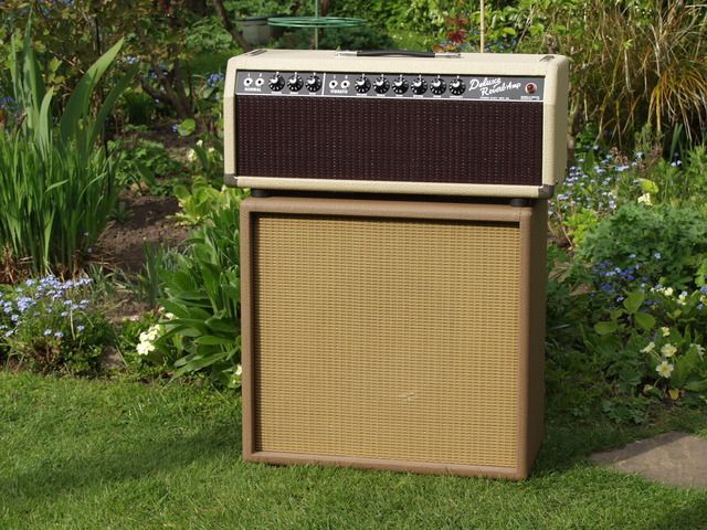
                    Not perfect bedfellows.. the cab was made for my Crate Blue Voodoo BV50 head, but fine for me. Spkr is a only a pretty poor 12" Peavey Blue Marvel 50w Im afraid.. until funds allow s'thing better.

                    Comment


                    • OK. Ive just measured V across both R's. I was expecting ~20v so set the DMM to VDC/ 200 but see 0.0V: the only reading I see on the DMM is right down at the 200mV setting..

                      V7, pin 8 = -6.6mV
                      V8, pin 8 = -5.1mV

                      Does that seem right-? the leads switched around give 6.6mV/ 5.1mV so whichever way round they're meant to be..

                      Comment


                      • I tried again with the bias pot turned 1/3rd rotation (from centre as it was) anti-clockwise. So approx 3/4 way 'Left'.

                        V8= 2.5mV

                        these readings dont seem right to me.. surely I should be looking at say 10mV max of bias pot dialed L, then 30mv max pot dialed other way. As an approx ballpark figure-to-expect that is-?

                        Comment


                        • Tried pot 3/4 way 'Right' (so there's only a very small ammount more I can dial the pot to max this way/ this side)..

                          V8= 7.8mV

                          I need some help. I dont understand a thing of these readings. Also the resisitors I have dont measure 1r. but 2.2r (each of the 10 in a strip.. and the colour codes, and listing are defo 1r).

                          Comment


                          • Originally posted by Sea Chief View Post
                            ...Is the idea with this test to twiddle the bias pot whilst measuring the voltage? or am I just taking a V reading for each power tube for now?
                            Let’s state that with more specific measurement references. You are adjusting the grid bias voltage while monitoring the plate current flowing through the tube. The plate current through each tube, in your case, is derived from the voltage across the 1Ω resistor you installed. Each mV across the 1Ω resistor corresponds to 1 mA flowing through the resistor. You complete the process by calculating the power dissipated in the tube which is plate voltage multiplied by the plate current flowing. For example 18mA X 425V would be 7.65 Watts dissipation. The plate voltage changes as the current changes so there is often some iteration required.


                            Originally posted by Sea Chief View Post
                            OK. Ive just measured V across both R's. I was expecting ~20v so set the DMM to VDC/ 200 but see 0.0V: the only reading I see on the DMM is right down at the 200mV setting..
                            V7, pin 8 = -6.6mV
                            V8, pin 8 = -5.1mV
                            Does that seem right-? the leads switched around give 6.6mV/ 5.1mV so whichever way round they're meant to be..
                            The mV readings are what you would expect.


                            Originally posted by Sea Chief View Post
                            I tried again with the bias pot turned 1/3rd rotation (from centre as it was) anti-clockwise. So approx 3/4 way 'Left'.
                            V8= 2.5mV
                            these readings dont seem right to me.. surely I should be looking at say 10mV max of bias pot dialed L, then 30mv max pot dialed other way. As an approx ballpark figure-to-expect that is-?
                            Normally the adjustment range would yield almost 0mA when the pot is turned fully counter clockwise and more than 25mA when turned fully clockwise. To clarify what is going on you should tell us the bias Voltage at pin(s) 5 of the power tube corresponding to the current readings and the plate voltage readings for each setting you try.
                            Last edited by Tom Phillips; 04-25-2015, 04:15 PM.

                            Comment


                            • Hi Tom,

                              but forgive me.. I dont know how I would be able to tell "the bias Voltage at pin(s) 5 of the power tube corresponding to the current readings and the plate voltage readings for each setting you try"

                              I thought thats what I was doing, I thought the bias voltage was ascertained by way of adding the 1r then measuring across, to read for eg 20mV. Using Ohms law the I= 20mV/1R (confusingly 2R.. so what do I do here?).. means 20mA.

                              Im utterly bewildered.

                              Comment


                              • These are going to be small ohm and DCV measurements so you do need to know what the default measure is for your meter. The default measure needs to be subtracted from your reading. With the meter set to DCV touch the probes together and wait for the reading to stabilize then record that number Now do the same for a low value resistance setting. Now do each again. If the readings come out the same (ish) you're good. If they don't, well, some lesser meters will do that and all hope of an accurate measure goes out the window.

                                First make sure the 1R resistors you bought off ebay are actually 1R. Let's assume they are for the moment. Now, with the amp on, in play mode, plugged into a load and all controls set to zero, measure the VDC across each 1R resistor. Don't forget to subtract your default figure.

                                The math for the 1R resistor (provided they are indeed 1R) is moot because 1mVDC measured equates to 1mA of current. So the mVDC reading across those resistors IS your mA of current. No need to use an ammeter at all.

                                Multiply the current figure and the plate voltage figure for the tubes watt dissipation at idle. "twiddle" the bias adjustment to get about 20mVDC across the resistors (20mA through the tube) You want to see about 7.5 to 8.5 watts.
                                Last edited by Chuck H; 04-25-2015, 04:18 PM.
                                "Take two placebos, works twice as well." Enzo

                                "Now get off my lawn with your silicooties and boom-chucka speakers and computers masquerading as amplifiers" Justin Thomas

                                "If you're not interested in opinions and the experience of others, why even start a thread?
                                You can't just expect consent." Helmholtz

                                Comment

                                Working...
                                X