Ad Widget

Collapse

Announcement

Collapse
No announcement yet.

Adding a trim pot in JTM45 --is it as simple as this?

Collapse
X
 
  • Filter
  • Time
  • Show
Clear All
new posts

  • Adding a trim pot in JTM45 --is it as simple as this?

    changing the 56k in the bias circuit to a 47k and adding a 22k resistor between the 47k and ground?

    I'm using exactly this schematic with KT66's, a slightly more filtering and wanting to add the bias pot. It's almost built, haven't finished the last couple details.

    http://www.classictubeamps.com/schem...66%20JTM45.pdf
    ~Semi-No0b Hobbyist~

  • #2
    You can replace the 56k bias resistor with a 30k resistor + 25k linear pot or trim pot wired as a variable resistor.

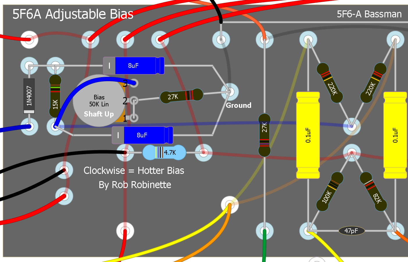
    The 5F6A Bassman uses the same bias circuit and here's my adjustable bias mod: https://robrobinette.com/5F6A_Modifi...djustable_Bias


    You can also do a dual pot bias control so you can balance unmatched power tubes: https://robrobinette.com/5F6A_Modifi..._Balanced_Bias
    https://RobRobinette.com/Amp_Stuff.htm

    Comment


    • #3
      robrob has it right. You need to reduce the size of the 56k resistor a little more to be sure you'll have enough adjustable range above and below that resistance value with the pot. The circuit he showed, however, doesn't allow any adjustment above the stock circuit. In fact it's less at only 55k. This is a very bad thing since many modern EL34's require more bias voltage than vintage tubes. You'd still be left unable to adjust the bias correctly! I don't recommend standard pots for bias circuits. Multi turn cermet pots are better. Use 47k for the pot/trimmer and Don't bother with 30k as an exacting alternate resistor value. I don't know why anyone does this, spec an odd value that isn't standard. Just use a 28k or 33k.
      "Take two placebos, works twice as well." Enzo

      "Now get off my lawn with your silicooties and boom-chucka speakers and computers masquerading as amplifiers" Justin Thomas

      "If you're not interested in opinions and the experience of others, why even start a thread?
      You can't just expect consent." Helmholtz

      Comment


      • #4
        I suggest a 30k resistor and 25k pot because it's been my experience that a 56k bias resistor sets a cool bias and you'll end up near the far end of pot travel to get 70% of max dissipation for 6L6GC tube. On my 5F6A Bassman with a Mercury Magnetics power transformer (60v AC bias tap) I had to drop the bias resistor down to 24k to be able to bias 6L6, 6V6, EL34 and KT88 tubes from 60 to 70%. I'm not a big fan of 50k of adjustment because it becomes too easy to go too hot on the bias.

        Last time I checked 30k was a standard resistor value.
        https://RobRobinette.com/Amp_Stuff.htm

        Comment


        • #5
          Originally posted by robrob View Post
          I suggest a 30k resistor and 25k pot because it's been my experience that a 56k bias resistor sets a cool bias and you'll end up near the far end of pot travel to get 70% of max dissipation for 6L6GC tube. On my 5F6A Bassman with a Mercury Magnetics power transformer (60v AC bias tap) I had to drop the bias resistor down to 24k to be able to bias 6L6, 6V6, EL34 and KT88 tubes from 60 to 70%. I'm not a big fan of 50k of adjustment because it becomes too easy to go too hot on the bias.

          Last time I checked 30k was a standard resistor value.
          No need to be snide. 30k is a standard value, but not a most standard value. Depending on how and where you source parts it's eminently easier to design with and use the standard 10X values because they are commonly stocked. I don't have a drawer on my bench for 30k resistors. I do have drawers for 3.3k, 33k, 330k, etc. My point was that it isn't necessarily a stringent spec. If, for example, mort also doesn't stock 30k resistors (unlikely), he may indeed have 28k or 33k on hand (more likely) and that would be fine rather than taking 30k as a stringent spec and either ordering it special or fussing with series or parallel resistors to try and meet that specific value.

          Good tip on the adjustability of the circuit. I wouldn't have thought it impossible to get the bias hot enough for 6L6GC's with a 30k load on the divider instead of the stock, fixed 56k value. Especially considering this circuit originally used 5881's or KT66's. But that was your amp. A a different amp. With different plate voltages. Certainly mort will have his own details to work out.

          And what's actually wrong with more adjustment if the fixed value bottoms within a safe-ish range for measurement? If I have a tube plugged in and it tests for even double the necessary current I would expect it to survive long enough for me to recognize and adjust the circuit. If it doesn't I don't even want that tube in there. More range allows the use of more tubes and more tube types without additional circuit modification.

          Oh well... If you're into a pissing match that's fine I suppose.
          "Take two placebos, works twice as well." Enzo

          "Now get off my lawn with your silicooties and boom-chucka speakers and computers masquerading as amplifiers" Justin Thomas

          "If you're not interested in opinions and the experience of others, why even start a thread?
          You can't just expect consent." Helmholtz

          Comment


          • #6
            I'm not looking for a pissing match I was just trying to explain the rational for my resistor and pot values but you make good points. A 27k resistor + 47k or 50k pot could be the way to go ensure the most power tube compatibility.
            Last edited by robrob; 08-30-2015, 02:43 PM.
            https://RobRobinette.com/Amp_Stuff.htm

            Comment


            • #7
              When we use the term standard values around here, we usually mean the values from the 5% chart. 1% parts are readily and cheaply available these days in all manner of what would have been odd values, but most people do not stock the set of 1% values.
              Education is what you're left with after you have forgotten what you have learned.

              Comment


              • #8
                See Standard EIA Decade Values For E-6, E-12, E-24, E-96, E-192 US Microwaves Application Note 108
                These days parts houses carry E96 resistor ranges as standard, but cap ranges may only be E3.
                A few decades ago E12 for both was more normal.
                My band:- http://www.youtube.com/user/RedwingBand

                Comment


                • #9
                  I'm just getting back to this particular project and this is where I'm at. My thinking was to use the stock bias circuit except be able to vary that last resistor by 22k only using two legs of the pot, so I laid it out as such but still need to change the 56k. Haven't fired it up yet. Will this work? Seems straight forward enough...

                  note: the cap on the right is grounded under the board


                  ~Semi-No0b Hobbyist~

                  Comment


                  • #10
                    robrob said it first and I backed it up. That answer has already been given.

                    Originally posted by Chuck H View Post
                    robrob has it right. You need to reduce the size of the 56k resistor a little more to be sure you'll have enough adjustable range above and below that resistance value with the pot... Just use a 28k or 33k... Use 47k for the pot/trimmer...
                    If you don't change the 56k you won't any adjustment for lowering the negative bias voltage (hotter). You would only have adjustment for increasing the negative bias voltage (cooler). To make the bias properly adjustable you need to use component values that allow the pot to alter the load both above and below the original load value of 56k. If the 56k resistor is still there you can only make the load resistance higher than 56k with the pot. You need to be able to adjust it both lower and higher. You need to replace the 56k resistor. Using a 22k trimmer (limited) you could replace the 56k resistor with a 47k. That would give you a load range of 47k to 69k. Which offers adjustment above and below the stock 56k value, but not much. IMHE it would be better to replace the 56k resistor with a 33k and replace your trimmer with a 47k. Allowing a load range of 33k to 80k.

                    The arrangement is almost correct. You need to join the eyelet where the pot and the filter cap meet to ground with the other filter cap and take your bias voltage from one of the eyelets the existing jumper is joining. Like this:
                    Attached Files
                    "Take two placebos, works twice as well." Enzo

                    "Now get off my lawn with your silicooties and boom-chucka speakers and computers masquerading as amplifiers" Justin Thomas

                    "If you're not interested in opinions and the experience of others, why even start a thread?
                    You can't just expect consent." Helmholtz

                    Comment


                    • #11
                      Originally posted by Chuck H View Post
                      robrob said it first and I backed it up. That answer has already been given.


                      If you don't change the 56k you won't any adjustment for lowering the negative bias voltage (hotter). You would only have adjustment for increasing the negative bias voltage (cooler). To make the bias properly adjustable you need to use component values that allow the pot to alter the load both above and below the original load value of 56k. If the 56k resistor is still there you can only make the load resistance higher than 56k with the pot. You need to be able to adjust it both lower and higher. You need to replace the 56k resistor. Using a 22k trimmer (limited) you could replace the 56k resistor with a 47k. That would give you a load range of 47k to 69k. Which offers adjustment above and below the stock 56k value, but not much. IMHE it would be better to replace the 56k resistor with a 33k and replace your trimmer with a 47k. Allowing a load range of 33k to 80k.

                      The arrangement is almost correct. You need to join the eyelet where the pot and the filter cap meet to ground with the other filter cap and take your bias voltage from one of the eyelets the existing jumper is joining. Like this:


                      Oh I see it now, his layout is the same as mine but with the pot and resistor swapped, which won't matter.

                      And yeah I plan on lowering it the resitor value and raising the pot value like you guys said, but just haven't gotten to it yet. And I did add a note that the caps' grounds are connected underneath and have put my bias jumper in.

                      I'm still kind of a paint by numbers builder and bias circuits are a little weird to me. Does it matter if the third leg of the pot isn't used? I'm using the center one and an outer one, so that the value increases with clockwise movement.
                      ~Semi-No0b Hobbyist~

                      Comment


                      • #12
                        Originally posted by mort View Post
                        And I did add a note that the caps' grounds are connected underneath and have put my bias jumper in.
                        Ah. Ok. I saw the one cap grounded at the pot bus and assumed the other was just floating. Ideally the two caps are grounded at the same location.

                        Originally posted by mort View Post
                        Does it matter if the third leg of the pot isn't used?
                        Yes. The CT is the most likely part of a pot to fail. That would leave you with no bias voltage at all and a potential instant and radical tube failure, jeopardizing other expensive components, before you could detect the problem. In reality the CT of a trimmer like that will PROBABLY never fail. But best practice dictates that you join the CT with the unused pot leg to ensure a more reliable voltage delivery.
                        "Take two placebos, works twice as well." Enzo

                        "Now get off my lawn with your silicooties and boom-chucka speakers and computers masquerading as amplifiers" Justin Thomas

                        "If you're not interested in opinions and the experience of others, why even start a thread?
                        You can't just expect consent." Helmholtz

                        Comment


                        • #13
                          Originally posted by Chuck H View Post

                          Yes. The CT is the most likely part of a pot to fail. That would leave you with no bias voltage at all and a potential instant and radical tube failure, jeopardizing other expensive components, before you could detect the problem. In reality the CT of a trimmer like that will PROBABLY never fail. But best practice dictates that you join the CT with the unused pot leg to ensure a more reliable voltage delivery.
                          I had always wondered why I would see bias pots wired like this because it wouldn't aid in general function but that makes perfect sense. Thanks for that. I just learned something.

                          Just powered it up as is and am getting -44v to -52v to the grids with no tubes installed. The window isn't huge but does that sound about right with 346/346vac coming off the transformer?
                          ~Semi-No0b Hobbyist~

                          Comment


                          • #14
                            That depends on a couple of things. Will the amp be tube rectified? Are you planning to use kt66's, 6l6's or el34's? And then, what specific model/brand? Tubes actually vary quite a lot. I'm not familiar with all of them, but even within the same brand there can be a lot of bias requirement difference from one specific model to the next. Even within the same tube designation. You don't know until you fire it up if the amp and specific tubes will sound best with a modest bias or a hot bias, etc. The best solution is to have enough range. -44 may be too much bias voltage for many el34's or kt66's and -52 may not be enough for some 6l6's.
                            "Take two placebos, works twice as well." Enzo

                            "Now get off my lawn with your silicooties and boom-chucka speakers and computers masquerading as amplifiers" Justin Thomas

                            "If you're not interested in opinions and the experience of others, why even start a thread?
                            You can't just expect consent." Helmholtz

                            Comment


                            • #15
                              It has JJ brand KT66's and a JJ GZ34S rectifier. I'll get it fired up tomorrow with tubes and see where everything is landing.
                              ~Semi-No0b Hobbyist~

                              Comment

                              Working...
                              X