 Tweet
Tweet
The bias on these things is always squirrelly to begin with. It's goes more negative in Standby mode, then settles down in Play mode. The zeners will make it more negative in Play mode. Check that the Voltage rating of the bias filter caps is not exceeded in both modes. That 150K 2W resistor in the bias supply runs hot and has usually drifted in older amps. Replace with two 2W flame proof resistors in series.
-
WARNING! Musical Instrument amplifiers contain lethal voltages and can retain them even when unplugged. Refer service to qualified personnel.
REMEMBER: Everybody knows that smokin' ain't allowed in school ! -
your saying i should replace rectifier diodes & replace it with modern spike protection . can't say I've seen any mods of it being replaced .Originally posted by g1 View Post
I think i will just replace the resistors for now .Not sure if this thing will ever be cranked wide open as i do have the master volume installed on it ."UP here in the Canada we shoot things we don't understand"Comment
-
Not the rectifier diodes. The spike protection diodes connected to the power tube plates that mozz mentioned.
It probably doesn't have them as most have gone bad by now and either been removed or replaced. The amp functions without them.
In the schematic you posted in post #8, they are the odd looking things across the output transformer primary, that look like back to back diodes.Originally posted by Enzo
Comment
-
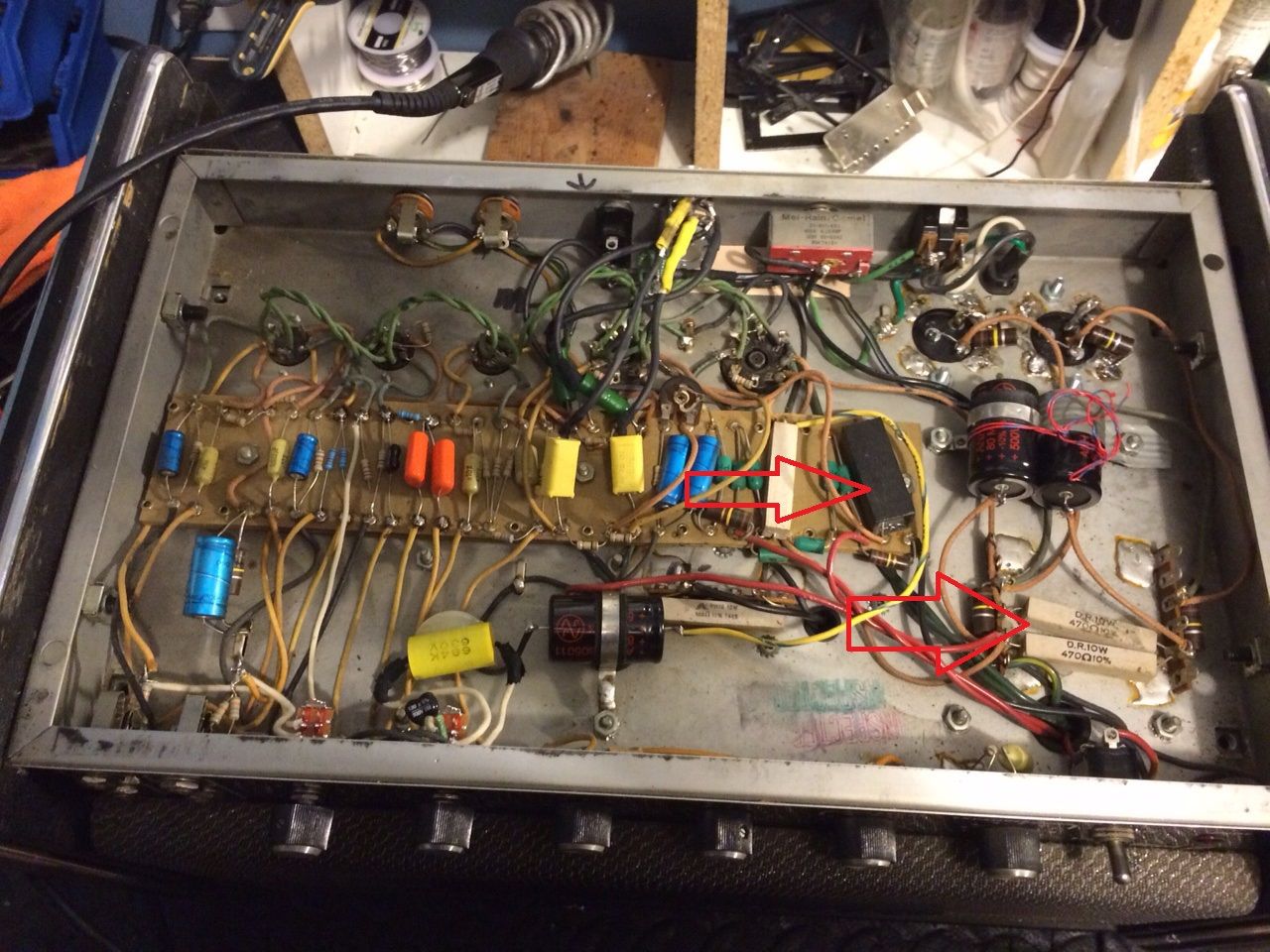
Right here , the black box , the second arrow is showing that it has 2 screen resistors in series
 "UP here in the Canada we shoot things we don't understand"
Comment
-
Yes, that black box is the TVS and should be removed.
The 2 series 470R 10W are shown on the schematic.
I would leave the first one in circuit (shown above R29 on schematic) and replace the second one (circled in post #8) with separate 1K's at each power tube socket.
I expect someone will correct me if there is a preferred method.Originally posted by Enzo
Comment
-
One thing i did not know ,my EXTECH 180193 LCR will read all the filter caps pretty accurately in circuit .....cool"UP here in the Canada we shoot things we don't understand"Comment
-
Filament voltage 3.27 vac at pin 2 & 7 I guess you multiply by 2 ? which would be 6.54vac
V5
3 =571
4=556
5,6=43
& same numbers on V4"UP here in the Canada we shoot things we don't understand"Comment
-
Right now i was going to add the grid resistors & any instructions on removing the TVS would be great"UP here in the Canada we shoot things we don't understand"Comment
-
No, you measure from pin 2 to pin 7 directly, that is what is powering the heaters. The reason you get half voltage from each end to ground is that you have a grounded center tap on the heater supply. Either a direct ground or a artificial center tap of two resistors.Filament voltage 3.27 vac at pin 2 & 7 I guess you multiply by 2 ? which would be 6.54vac
One certainly hopes that pin 5 voltage is NEGATIVE 43 volts. Polarity matters, always include it.Education is what you're left with after you have forgotten what you have learned.Comment
-
6.56 Volts ac & pin 5 =-43 voltsOriginally posted by Enzo View Post
thanks I was getting to add the grid/screen resistors 1k 5 watt Ceramic resisters across pin 6 & 4 . do you agree with this ?"UP here in the Canada we shoot things we don't understand"Comment
-
There is a small resistor (1.5k i believe) across pin 5 & 6
i was going to use pin 6 with 4 for my screen resistor but I'm not sure it that's the best route .Last edited by copperheadroads; 09-24-2016, 12:47 PM."UP here in the Canada we shoot things we don't understand"Comment
-
Yes, using pin 4 & 6 for the screen resistors is the best way. Lift the grid resistors from pin 6 that are there now. The larger resistors need the support more than the grid stoppers do. You can use the Marshall style wiring like this:
As far as the TVS, you can just remove it. If you want to retain spike protection, use the diode method like in newer Fender amps. They use a 3000V diode reverse biased from power tube plate to ground, like this:
If you don't have 3000V diodes, you can use three 1000V in series on each side. 1n4007 for example.Originally posted by Enzo
Comment
-
Hi Guys
Tubes maintain their voltage withstand capability their entire life. The parameter that changes is the cathode emission goes down over time. In a YBA-1A the tubes will last forever as long as they are not mechanically upset. So, there is no need to change the supply voltage unless you simply must do so for your own aesthetic reason.
-43V seems a bit low for control voltage in a 560V amp. Ideally, there should be 15-20% of available bias sweep, based on the absolute value for the screen voltage. With 560V one would hope to have a bias sweep that extends to -100V if you want to be able to control any tube sample. You can use 6L6GCs or 6550s in here, too.
Ideally, one would have individual bias pots for each tube, which is an easy mod to do. Split the V formed by the two 220k grid-leaks on the board and feed the freed ends from the wipers of two 25k pots wired in parallel: pot-X together, pot-0s together. Tie pot-X to ground through a 6k8 resistor and tie pot-0 to the second bias filter cap. Check the bias sweep WITHOUT TUBES and make sure that the bias voltage appears at pin-5 of each tube socket.
The stock standby is in the CT of the plate winding. If you MUST have a standby, move it to the cathodes of the tubes. There is no real reason to retain this switch.
Simply snip out the varactors as others have said above. They lose their effectiveness over time anyway.
if you want to extend tube life, simply reduce the idle current so the tubes heat up less. The fan gets rid of heat quitre well and that improves their life expectancy more than anything else.
If you want to have a quieter fan, you can reduce the voltage to it and it will run slower but still move tonnes of air.
Have funComment
-
Finally finish the mods following the jcm 2204 layout & it really sounds great ,I still have to do what is recommended . clip the tvs & add screen resistors .
strange thing now my master volume don't turn all the sound off & is quite loud when all the way down . it is the ken ficsher style PPIMV not the lar-mar PPIMV"UP here in the Canada we shoot things we don't understand"Comment
-
Is that the same as this one?
Comment

Comment