Ad Widget

Collapse

Announcement

Collapse
No announcement yet.

What diodes to use for a Marshall 2204 build

Collapse
X
 
  • Filter
  • Time
  • Show
Clear All
new posts

  • What diodes to use for a Marshall 2204 build

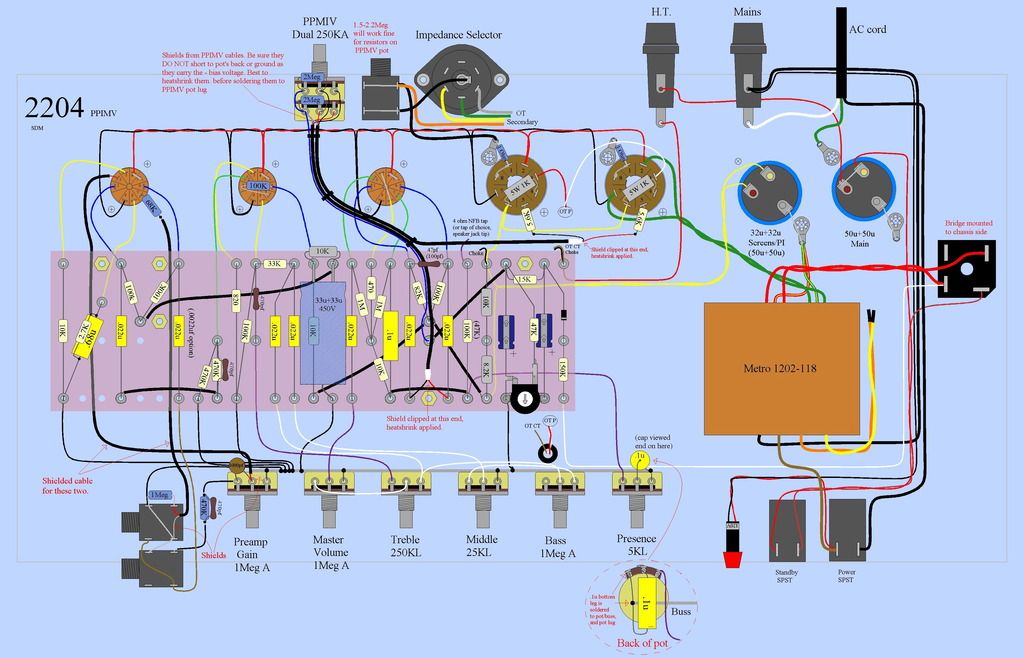
    I'm ordering the rest of the parts to get started on my 2204 build & I'm not 100% sure what diodes to use my 290gx tranny from Hammond, it has the same wiring as the layout I will be using .
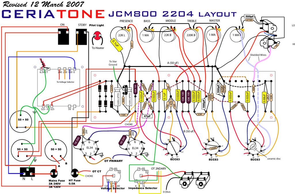
    Also the 5k6 grid stoppers i believe they are? in the layout i couldn't source a 2 watt in 5k6 value at Ce distribution only had 5.1k or 6.2k what would you recommend in this position ?
    https://www.cedist.com/search/node/diodes%20
    "UP here in the Canada we shoot things we don't understand"

  • #2
    I've always used the 4007 rectifier diodes, they are more than adequate for a 2204 build.
    "If Hitler invaded Hell, I would make at least a favourable reference of the Devil in the House of Commons." Winston Churchill
    Terry

    Comment


    • #3
      Originally posted by copperheadroads View Post
      Also the 5k6 grid stoppers i believe they are? in the layout i couldn't source a 2 watt in 5k6 value at Ce distribution only had 5.1k or 6.2k what would you recommend in this position ?
      Grid stoppers should be carbon comp, and half a watt is plenty. No idea why Ceria uses 2 watt parts. I think you'll find Mouser has 'em. Value isn't all that much an issue, you could use 5k1 or 6k2 no problem. Any value cc you have on hand, matched to say 5%, 4k7 up to 10K I'm sure would work just fine.
      This isn't the future I signed up for.

      Comment


      • #4
        Hi
        Speaking for myself, but I think others agree, most technicians prefer a schematic rather than a layout.

        Plain old vanilla 1N4007 would be my first pick, for your - I assume - HV rectifiers.


        CE is a good place to source amp-specific parts, but for resistors, I shop at places like Mouser. Uless I am missing something, I am unsure why we need 2 watt resistors in a control grid circuit.
        Education is what you're left with after you have forgotten what you have learned.

        Comment


        • #5
          Thanks that should be these ? & 1amp is suitable ?
          https://www.cedist.com/products/diode-1a-1000v
          "UP here in the Canada we shoot things we don't understand"

          Comment


          • #6
            Yes.
            Education is what you're left with after you have forgotten what you have learned.

            Comment


            • #7
              I used these two several times.
              http://site.triodestore.com/JCM8002204Stock.pdf
              http://el34world.com/charts/Schemati...l_50w_2204.pdf
              I used the 1 watt 5k6 resistors.
              If you lack Can cap space, I used JJ, 1- 100/100uf can cap, and 1- 40/20/20/20uf, instead of the 3- 50/50uf Cans.
              Gives a lot of cap flexibility.
              T
              "If Hitler invaded Hell, I would make at least a favourable reference of the Devil in the House of Commons." Winston Churchill
              Terry

              Comment


              • #8
                I like this layout as well as it has the ppimv as i will be doing as well plus a resonance/depth control on the back but some values are not shown in this layout .

                3 50/50 can style with the clamp going installed on top of the chassis ,the can for the preamp will probably go on the chassis directly under the turret board .
                "UP here in the Canada we shoot things we don't understand"

                Comment


                • #9
                  I may post this in another thread but i may leave enough room on the end to add an another preamp tube in the future . I was going to build a hot rodded SIR #36/AFD style amp but for now i think i will go close to stock & play with different values so if any one has an opinion on what the like to improve the tone let me know
                  "UP here in the Canada we shoot things we don't understand"

                  Comment


                  • #10
                    That layout is fine, except for the placement of the PPIMV.
                    You want that on the front if you have room for it.
                    There are a lot of variations of the marshall 1987 circuit.
                    Another one to get ideas from is the TubeDepot layout.
                    Layouts, and schematics are on the bottom of the page.
                    https://tubedepot.com/products/class...r-amp-kit-head
                    T
                    **If you haven't built your board yet?
                    I recommend putting all straps and leads on the top of the board.
                    It makes trouble shooting, changes, and modifications much easier, after it is all built and put together.
                    Last edited by big_teee; 03-18-2017, 04:46 PM.
                    "If Hitler invaded Hell, I would make at least a favourable reference of the Devil in the House of Commons." Winston Churchill
                    Terry

                    Comment


                    • #11
                      Originally posted by copperheadroads View Post
                      so if any one has an opinion on what the like to improve the tone let me know
                      Many of my customers found their 2204 and similar Marshalls to be way scratchy-bright. Note at the volume control, there's a peaking cap (470pF) feeding it, and a brightening cap across hot to wiper. You can eliminate either or both, also alter their values to suit your ear. Another 470 pF peaker is on the way to the EQ drive grid. Here also you can clip it out or adjust to taste.

                      Some like to parallel a cap across the EQ drive cathode R, typically a 1K or 820 ohm resistor. By selecting cap value you can create a hi boost, mid & up boost, or full range boost. Similar with the 10K resistor in the 2nd stage preamp.

                      Also popular to mod the EQ stack. You can change the slope resistor and/or treble cap to suit your ear.

                      Have fun!
                      This isn't the future I signed up for.

                      Comment


                      • #12
                        Originally posted by Enzo View Post
                        Speaking for myself, but I think others agree, most technicians prefer a schematic rather than a layout.
                        Yes, a schematic for analyzing a circuit but I always need to find or draft a layout drawing for the actual build. A google search turned up this schematic from M. Huss...


                        Click image for larger version

Name:	JCM800_2204.gif
Views:	9
Size:	196.1 KB
ID:	845028

                        Steve A.

                        P.S. I tried attaching the image file (#42803) but there is nothing attached to the actual post. (If you click on "Reply to post" you can see the code for the attachment but nothing is displayed.)

                        Anybody else experiencing that problem today?
                        Last edited by Steve A.; 03-18-2017, 08:54 PM.
                        The Blue Guitar
                        www.blueguitar.org
                        Some recordings:
                        https://soundcloud.com/sssteeve/sets...e-blue-guitar/
                        .

                        Comment


                        • #13
                          Steve, yes a layout is fine for building something, but it makes it hard to see circuit relationships. And that is especially important when asking about circuit values. perhaps i should have said technicians prefer schematics for circuit discussion.
                          Education is what you're left with after you have forgotten what you have learned.

                          Comment


                          • #14
                            For what it's worth, I remember reading somewhere that 2W carbon comps in particular have much less noise than even 1/4 or 1/2W.
                            If I have a 50% chance of guessing the right answer, I guess wrong 80% of the time.

                            Comment


                            • #15
                              Originally posted by SoulFetish View Post
                              For what it's worth, I remember reading somewhere that 2W carbon comps in particular have much less noise than even 1/4 or 1/2W.
                              As noise is related to heat, I'm sure that's true. A larger resistor will be able to dissipate heat better, minimizing noise ascribed to temperature. However, grid stoppers are not in a position to have any worries about creating heat, there's practically no voltage across them. If you happen to have a pile of 2W cc's hanging around looking for something to do, be my guest. FWIW last time I went shopping for 5K6 cc's I found a stash of 1W parts for cheap. For grid stopper functions, low power cc's work just fine.
                              This isn't the future I signed up for.

                              Comment

                              Working...
                              X