To be more specific: You should have all three wires from the 2x 350V secondary be routed together to the HT PCB. Make a three wire twisted bundle, like the heater wiring. This will vastly reduce the magnetic noise flux from the secondary HT transformer wiring.
Ad Widget
Collapse
Announcement
Collapse
No announcement yet.
Yup, Another One... Kraken 50 Build: Round II
Collapse
X
-
Hi T.T., question for you, if you don't mind. If the CT's are routed to the neg terminal on the first filter cap, there is still a wire running from that point to chassis ground, on many amps. What would you do with that ground wire? (Sorry, very new to all this here)Originally posted by Thoriated Tungsten View PostNice work. I would recommend moving the center tap of your 2x 350V secondary over to the HT PCB. Specifically the negative terminal of the first filter cap, right after the rectifiers. There are exactly zero good reasons to have the ripple current from the HT supply flow through the chassis. Make the HT supply PCB be completely 'floating', then route ground and HT to the rest of the amp.The only good solid state amp is a dead solid state amp. Unless it sounds really good, then its OK.
Comment
-
Somebody write a long post, I can't remember where. I don't know if they are a guru or not. They said, for the Fender style chassis anyway (and I know this is not that style), there were two main ground points. One near the power transformer, that had the HV stuff grounded directly to the chassis. Another on that brass plate that the pots and input jacks mount to, that the low signal wiring (input jacks, preamp tubes) get grounded to. They said that the eddy currents were separated enough, first since there are two different pieces of metal (the steel chassis, and the brass plate), and 2 they were grouped together in separate areas of the amp, that the amp would still be OK for hum and noise due to ground loops. Admittedly, I don't have the physics chops at hand to be able to understand this argument fully. Was it a baloney argument?The only good solid state amp is a dead solid state amp. Unless it sounds really good, then its OK.
Comment
-
HT PCB? The PCB in this amp is not HT. IT's DC rectification for V1/V2 filaments. Maybe I'm misunderstanding...Originally posted by Thoriated Tungsten View PostNice work. I would recommend moving the center tap of your 2x 350V secondary over to the HT PCB. Specifically the negative terminal of the first filter cap, right after the rectifiers. There are exactly zero good reasons to have the ripple current from the HT supply flow through the chassis. Make the HT supply PCB be completely 'floating', then route ground and HT to the rest of the amp.
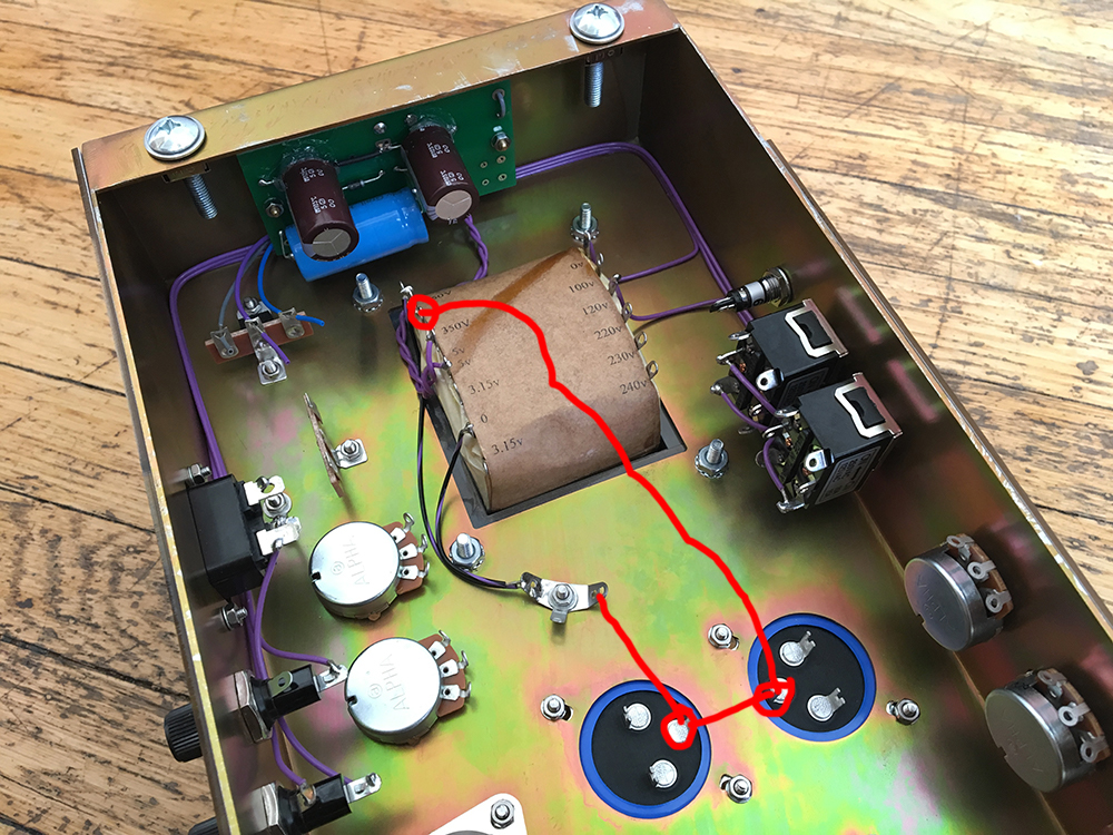
You're saying to route PT secondary CT like this?

Comment
-
I ordered the chassis, turret board, and a few of the miscellaneous parts like jacks and tube sockets and switches. Everything else, I sourced. You can buy a full kit from Ceriatone. But I'm not building the stock Chupa/Yeti. These are slightly different.Originally posted by mikepukmel View PostAs an aside, FourT6and2, did your Cereatone kit come with all of the discrete parts, or did you source them yourself?
Comment
-
Run CT wire dirctly to minus pole of first filter cap. then also another short wire from those terminal to the chassis. Those link to the ground is just to provide a ground reference . Do not run high ripple current through it. The power supply return current should run just from first cap to CT but not through chassis. If you use the chassis as signal return you will not modulate the signal with high noisy ripple, meant 100/120 cps humLast edited by catalin gramada; 08-05-2017, 03:29 PM."If it measures good and sounds bad, it is bad. If it measures bad and sounds good, you are measuring the wrong things."
Comment
-
Sorry, I'm confused.Originally posted by catalin gramada View PostRun CT wire dirctly to minus pole of first filter cap. then also another short wire from those terminal to the chassis. Those link to the ground is just to provide a ground reference . Do not run high ripple current through it. The power supply return current should run just from first cap to CT but not through chassis
"Run CT directly to negative terminal on first cap": OK
"Then another short wire from those terminals (PLURAL?) to the chassis": What terminals? There's only one... We are talking about the negative terminal on the first cap. What other terminals are you talking about?
"Do not run high ripple current through it." What? Through what?
"Power supply return current should run just from first cap to CT but not through chassis": But you just said, "then another wire from those terminals to the chassis."
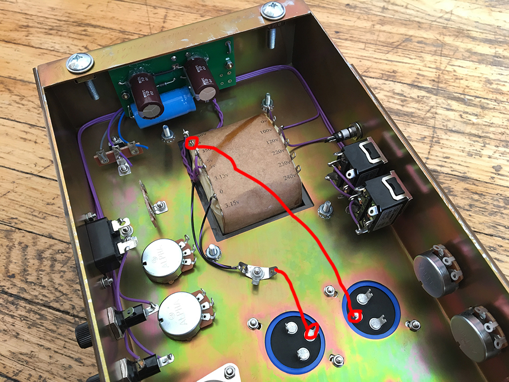
Like this???? This looks problematic to me. How is the filter cap supposed to bleed to ground when you turn the amp off?

Comment
-
Thanks!Originally posted by FourT6and2 View PostI ordered the chassis, turret board, and a few of the miscellaneous parts like jacks and tube sockets and switches. Everything else, I sourced. You can buy a full kit from Ceriatone. But I'm not building the stock Chupa/Yeti. These are slightly different.The only good solid state amp is a dead solid state amp. Unless it sounds really good, then its OK.
Comment
-
Yeah, I think this is what Catalin meant. CT wires to cap neg, then short wire cap neg to chassis.Originally posted by FourT6and2 View PostHT PCB? The PCB in this amp is not HT. IT's DC rectification for V1/V2 filaments. Maybe I'm misunderstanding...
You're saying to route PT secondary CT like this?

Catalin: the 0 (HV CT) would also go to the - cap as well, right?The only good solid state amp is a dead solid state amp. Unless it sounds really good, then its OK.
Comment
-
Why is this any better than CT directly to ground though? It looks like you get the same result either way. The CT is still going to ground. The cap negative terminal is still going to ground. I'm a bit confused. Aiken has this to say on his website:Originally posted by mikepukmel View PostYeah, I think this is what Catalin meant. CT wires to cap neg, then short wire cap neg to chassis.
Catalin: the 0 (HV CT) would also go to the - cap as well, right?
"If you look at the schematic for an amplifier, you will see the capacitors are arranged in a line or series configuration, or sometimes in a parallel or "branch" configuration. Usually the series connection is used, because it provides better filtering as you go down the line. The ground connections of these caps are the star points in multiple-star systems. The first cap ground is the first star point (or the only star in a single-star ground system). It should be physically located closest to the power transformer center-tap. The power transformer center-tap wire should be soldered directly to the ground lug of this cap, and a very short, heavy wire should run from there to the chassis ground connection (if there is one). Do not connect the power transformer center-tap to the chassis and the first cap ground to the chassis at a different spot; this will cause heavy ground current flow in the chassis."
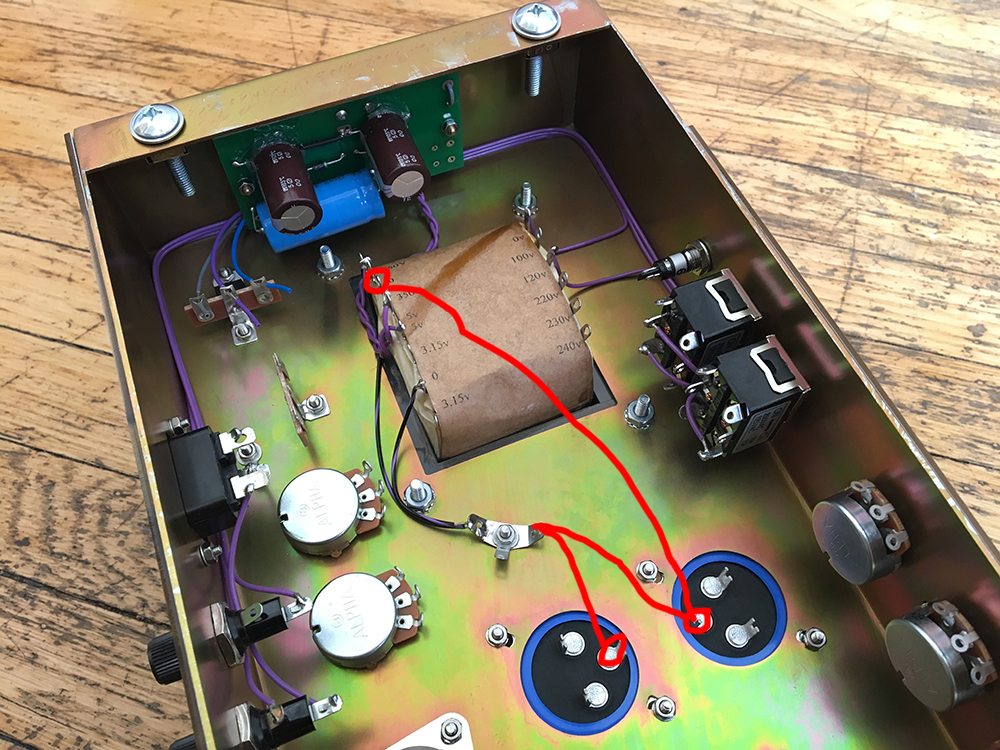
So Aiken says it should be like this:

Comment
-
Yes, exactly like that. Have the two 350V phases follow the first red line from the transformer to near the first filter cap (the one to the right in your photo) for as long as possible. Hopefully the 'right side' cap is also the one you intend to use as the first filter cap after the rectifier.Originally posted by FourT6and2 View PostHT PCB? The PCB in this amp is not HT. IT's DC rectification for V1/V2 filaments. Maybe I'm misunderstanding...
You're saying to route PT secondary CT like this?

Yes, I was confused by your low voltage PCB, as I thought the pair of twisted purple wires going to it were connected to the 350V phases. I have now spotted the HT diodes on the turret board.
Comment
-
Wish I knew!!Originally posted by FourT6and2 View PostWhy is this any better than CT directly to ground though? It looks like you get the same result either way. The CT is still going to ground. The cap negative terminal is still going to ground. I'm a bit confused. Aiken has this to say on his website:
"If you look at the schematic for an amplifier, you will see the capacitors are arranged in a line or series configuration, or sometimes in a parallel or "branch" configuration. Usually the series connection is used, because it provides better filtering as you go down the line. The ground connections of these caps are the star points in multiple-star systems. The first cap ground is the first star point (or the only star in a single-star ground system). It should be physically located closest to the power transformer center-tap. The power transformer center-tap wire should be soldered directly to the ground lug of this cap, and a very short, heavy wire should run from there to the chassis ground connection (if there is one). Do not connect the power transformer center-tap to the chassis and the first cap ground to the chassis at a different spot; this will cause heavy ground current flow in the chassis."
So Aiken says it should be like this:


 The only good solid state amp is a dead solid state amp. Unless it sounds really good, then its OK.
Comment
-
So which of these two is better?Originally posted by Thoriated Tungsten View PostYes, exactly like that. Have the two 350V phases follow the first red line from the transformer to near the first filter cap (the one to the right in your photo) for as long as possible. Hopefully the 'right side' cap is also the one you intend to use as the first filter cap after the rectifier.
Yes, I was confused by your low voltage PCB, as I thought the pair of twisted purple wires going to it were connected to the 350V phases. I have now spotted the HT diodes on the turret board.


Comment
Comment