Announcement

Collapse
No announcement yet.

Roberts Tape Amp Conversion

Collapse
X
 
  • Filter
  • Time
  • Show
Clear All
new posts

  • Roberts Tape Amp Conversion

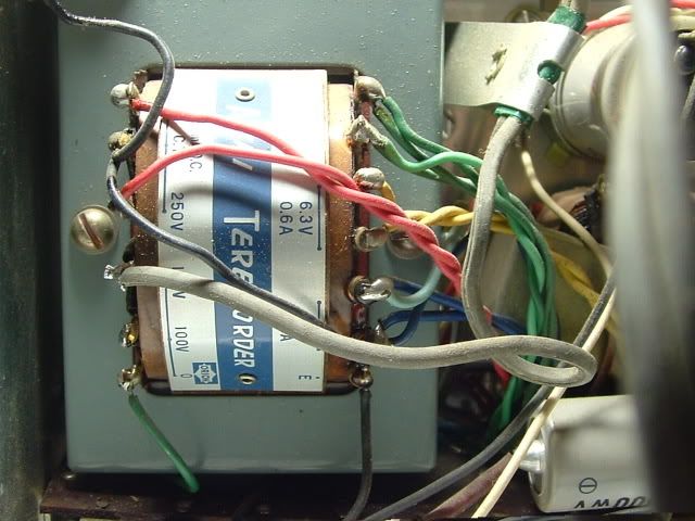
    I am looking at making a Kalamazoo M1 out of this and have just gutted and rewired the PT and line power for a grounded supply voltage. I need some input on the voltages that are present with no load. First off is it OK to power up the amp with no load on the power tranny?

    Also, if anyone would like to look over my board layout compared to the schematic I can post that as well.

  • #2
    Not sure what model you have but if its a 770 or 771 or 925, etc, then you have the same trannies that are in my Akai M6 and M7 decks. 6X4, 6BQ5, 6267, 12AD7?
    If so, I can share my results after two conversions to AX84 High Octanes. I used solid state rectifiers and got 307 VDC when loaded. If I were to do it again I would use the 6X4 and get the voltage drop. I wound up using a 6V6 on one of them, then on the second one I placed an octal socket and a 9 pin mini, to swap between 6V6 and 6BQ5.

    I say "yes" about measuring intital voltages unloaded - I did it without incident.

    I think you will be very pleased converting yours to a Kalamzoo Model 1. These are fun circuits that sound terrific while keeping the police visits to a minimum.

    RWood

    Comment


    • #3
      Kalamazoo

      Yea, the Kalamazoo was the closest configuration I could find to the original tube compliment. I will be using the 6X4 rectifier in the power section.

      I am measuring 7v across the heaters with no load and 560V across the two red leads to the rectifier. I am assuming that would be 280-0-280 for the PT output. Looks like they are about spot on for a Kalamazoo conversion.

      Hmm....If I measure one leg of the heater winding to ground I get 120V? Is that normal?
      Last edited by Rockn; 08-18-2009, 01:02 PM.

      Comment


      • #4
        You should be getting approx. 3.15 VAC from one leg of the filament supply to ground.

        Is this the PT you have?

        Comment


        • #5
          Windings

          Mine has a red pair, blue pair and a yellow pair. I was assuming the blue was a 6.3V pair since they were connected to the heaters previously. The model tape player I am converting is a 90C. It is the one with the built in speaker. I can post pics if it helps. Thanks again for the response.

          Comment


          • #6
            Here'a better picture. http://i32.photobucket.com/albums/d2...chassis016.jpg

            On mine, there are three filament sets: green wires for the 6267 heater, yellow for the 6X4 and blue for the 12AD7, 6BQ5 and 6AR5. As you can see, the green and blue sets go to separate hum pot / artificial center taps. The red pair is for high voltage to the rectifier plates.

            I am not familiar with the 90C - do you have a link to the schematic?
            Also, note that the Vox AC-4 has the same tube lineup, at least to the Akais I am using. There are some Selmer amps that use that lineup, too, although the Kalamazoo will do you fine.

            Comment


            • #7
              This amp had a complement of 2 - 6AU6, 1 - 6X4, 1 - 6BQ5 and a 6AR5. One would assume that the hookup would be similar with the yellow supplying the 6X4 and the blue taking care of the other tubes. I have no schematic, but it is similar with the exception of the 300 ohm pots.

              Comment


              • #8
                Okay, different preamp tubes from mine but otherwise very similar. I agree with what you suggest about which pair goes where.

                Are you getting 6 to 7 VAC when you measure blue/blue and also yellow/yellow?

                Comment


                • #9
                  Windings

                  Yes, I get the same voltages across both pairs. I suppose I would take the one with the highest current and use it for the two tubes and the lower current for the rectifier. Just wondering why I would get 110 v with just one side of the tap to ground.

                  Comment


                  • #10
                    Almost done

                    This thing is finally almost done. Just waiting on some new pots and looking for a decent 8" speaker. It sounds pretty good even through a 6" speaker and with a little tweeking will probably sound even better. This thing is so simple, but good things usually are.

                    Comment


                    • #11
                      The 120VAC or so you are measuring from one side of the heater winding to ground is caused by capacitive coupling of the windings inside the transformer. This really causes a lot of hum in a preamp if you don't create an artificial center tap. But don't use an artifical center tap on the winding that goes to the 6X4. From the data sheet it looks like one side of that 6.3V winding need to go to B+.
                      WARNING! Musical Instrument amplifiers contain lethal voltages and can retain them even when unplugged. Refer service to qualified personnel.
                      REMEMBER: Everybody knows that smokin' ain't allowed in school !

                      Comment


                      • #12
                        "Farting" out problem lwer strings

                        OK, there are a few mods to the standard M1 schematic. I added a hi and low input with a 1 meg resistor to ground at the first grid. I also added cathode bypass caps on both 12ax7 cathodes and the EL84. It was farting out really bad prior to adding the bypass caps and now it only happens on the high gain input. I think my voltages are a bit higher than stock on all sections by about 20V which seems to be fine aside from the bass frequencies causing the aforementioned farting. The tone is pretty well controlled and the higher frequencies are really pretty clean. Any input would be appreciated. It seems the tone control also has an affect on this, when it is at 10 it is full on gas attack.
                        Last edited by Rockn; 10-14-2010, 03:05 AM.

                        Comment


                        • #13
                          Have you played it through a few different speaker arrangements? I'd rule that in or out before changing the circuit.

                          But if you do there are different values of coupling caps, different values of bypass caps that will affect the bass frequencies that pass though. A decade box for capacitors is great for tweaking values.

                          It's also possible that your layout is resulting in some oscillation, and the audible results are only heard when you have the amp cranked.

                          Got any pictures?


                          RWood

                          Comment


                          • #14
                            I have it going through a 4x12 Marshall at the moment and it is not the sound of a speaker rattling or buzzing. I was thinking it was the preamp overdriving the power tube so I tried some lower gain tubes and the problem persists. I will take some voltages again and see what the EL84 is biased at. It is pretty much a stock M1 layout with the exception of the bypass caps and it sounds great except when it gets to the one point on the tone pot and the lower frequencies. No pics at the moment.

                            Comment

                            Working...
                            X