Announcement

Collapse
No announcement yet.

Hammond H-AO-44-1 Conversion (Help)

Collapse
X
 
  • Filter
  • Time
  • Show
Clear All
new posts

  • Hammond H-AO-44-1 Conversion (Help)

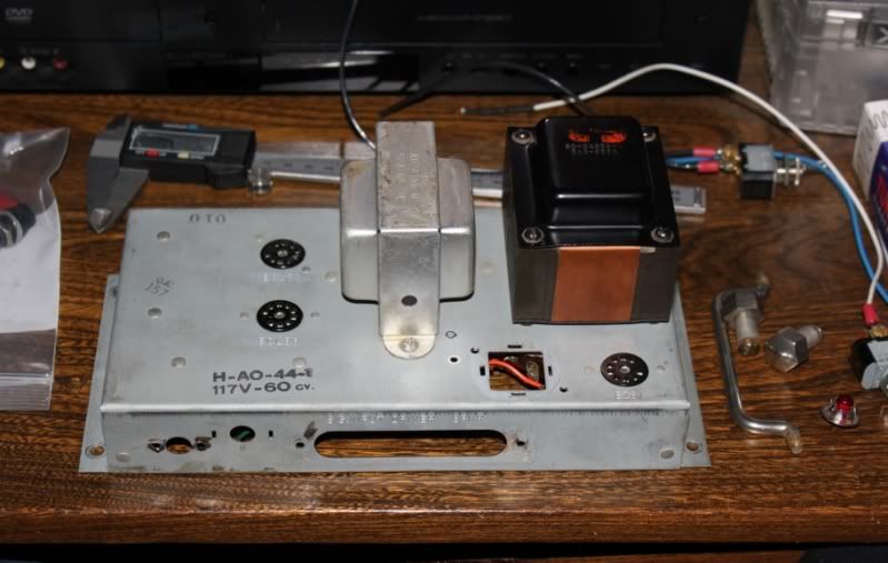
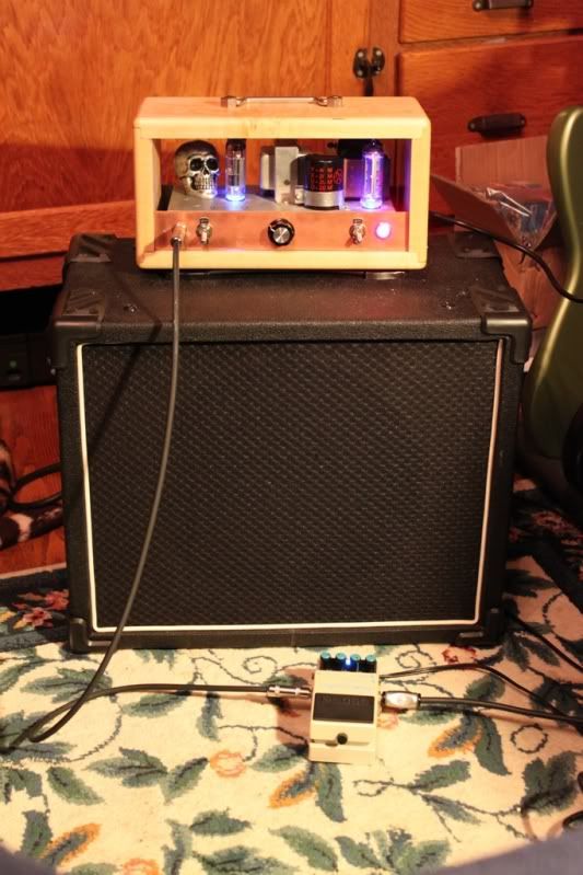
    I came across on of these little guys and picked it up, it use to be a reverb driver out of a Hammond organ.
    I found this conversion for it and got to work. I dubbed mine "The Organ Donour"

    Paul Ruby Amplifiers

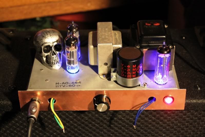
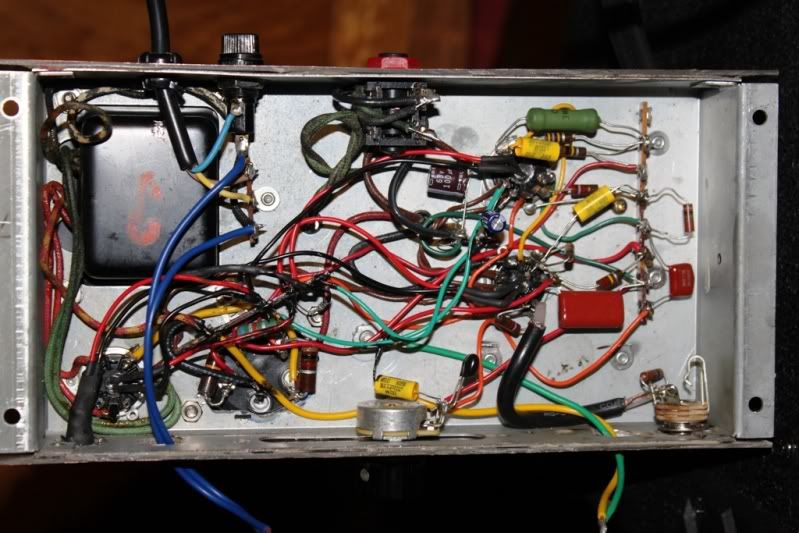
    I got mine up and running, the only thing isn't right is the volume control. When its all the way down, it sounds like its at quarter, it doesnt go quiet. I cleaned the pot and made sure there was no shorts and triple checked the Schem. I dont know what that could be.

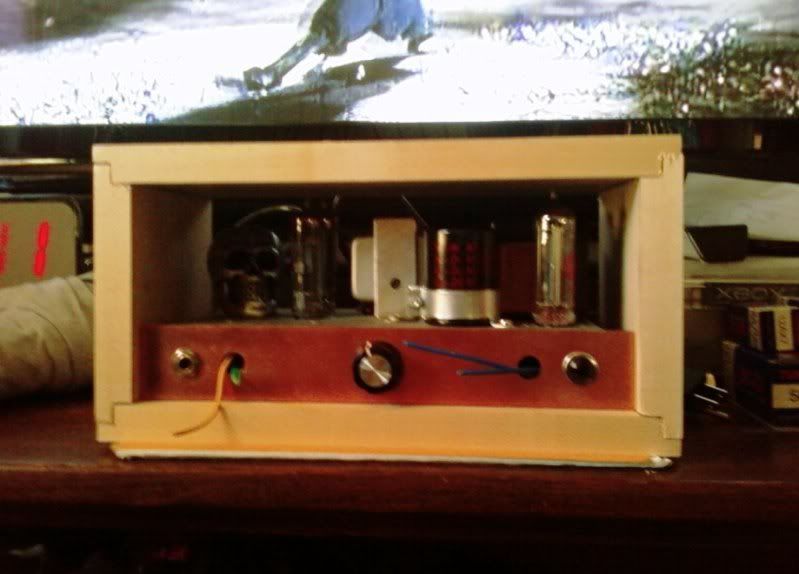
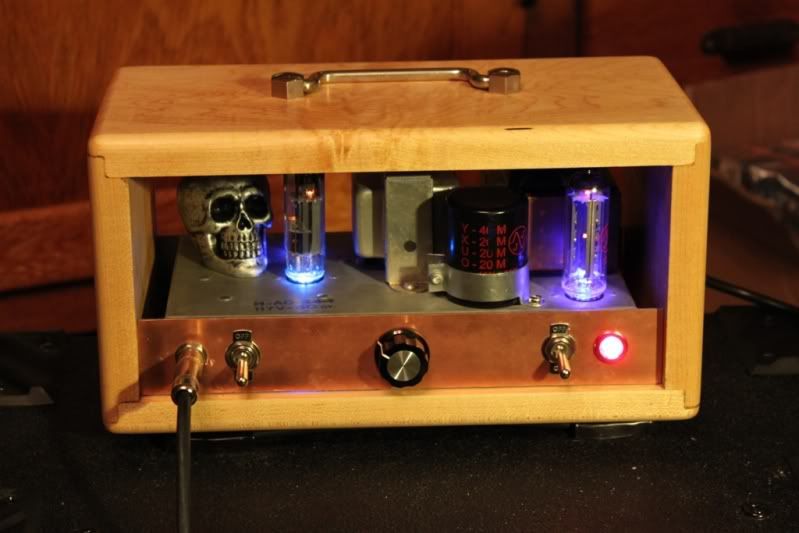
    I used blank copper circuit board to make a nice face plate. Im still waiting on a couple switched to come in. its going to have a maple cab which isnt glued yet in this picture. Ill post more pics when im done.


  • #2
    Did you wire it up like the Ruby schematic? That schematic has a 1K resistor connected to the low side of the volume control. Kind of unusual but that's why the Volume control won't shut the signal off. Try soldering a jumper wire across the 1K.
    WARNING! Musical Instrument amplifiers contain lethal voltages and can retain them even when unplugged. Refer service to qualified personnel.
    REMEMBER: Everybody knows that smokin' ain't allowed in school !

    Comment


    • #3
      Originally posted by loudthud View Post
      Did you wire it up like the Ruby schematic? That schematic has a 1K resistor connected to the low side of the volume control. Kind of unusual but that's why the Volume control won't shut the signal off. Try soldering a jumper wire across the 1K.
      Yeah that made the volume at zero decrease abit but not completely. should i oust that 1k or find a lower value that eliminates the volume at zero?

      Comment


      • #4
        Re-wire the volume pot like the schematic below. The added capacitor between the volume control and the 2nd tube can be any value between 20nF and 1nF. It should have 400V or higher voltage rating.
        Attached Files
        WARNING! Musical Instrument amplifiers contain lethal voltages and can retain them even when unplugged. Refer service to qualified personnel.
        REMEMBER: Everybody knows that smokin' ain't allowed in school !

        Comment


        • #5
          Originally posted by loudthud View Post
          Re-wire the volume pot like the schematic below. The added capacitor between the volume control and the 2nd tube can be any value between 20nF and 1nF. It should have 400V or higher voltage rating.
          Much appreciated. Im not learned enough to know but will this change the tone any?

          Comment


          • #6
            Probably not a noticable amount.
            WARNING! Musical Instrument amplifiers contain lethal voltages and can retain them even when unplugged. Refer service to qualified personnel.
            REMEMBER: Everybody knows that smokin' ain't allowed in school !

            Comment


            • #7
              Originally posted by loudthud View Post
              Probably not a noticable amount.
              Works like a champ. Thank you very much.
              and that concludes the electronics portion of this build. On to the wood housing.


              Comment


              • #8
                Done, sounds great
                Thanks for the help.


                Comment


                • #9
                  Oh...I love this!
                  Can I say it?

                  It's cute as hell!!!

                  Great work.

                  Comment


                  • #10
                    Shouldn't you have a light inside the skull?
                    WARNING! Musical Instrument amplifiers contain lethal voltages and can retain them even when unplugged. Refer service to qualified personnel.
                    REMEMBER: Everybody knows that smokin' ain't allowed in school !

                    Comment


                    • #11
                      yeah i could throw a couple red LEDs in the eye sockets. that would be really heavy metal, but that doesnt match the tone of the amp, i use a hollow body with a SD jazz pick up in the neck. The skull fills up the empty spot cause my girlfriend really likes skulls.

                      Comment


                      • #12
                        I know this is an old thread, but I'm starting a AO-44 conversions ala Paul ruby as well. Just wondering what the yellow and green wires running out to the switch on the face plate are for? Looks like you're running one of the caps to ground.

                        Originally posted by NFXP View Post
                        Works like a champ. Thank you very much.
                        and that concludes the electronics portion of this build. On to the wood housing.


                        Comment


                        • #13
                          Originally posted by lyngaaskhan View Post
                          I know this is an old thread, but I'm starting a AO-44 conversions ala Paul ruby as well. Just wondering what the yellow and green wires running out to the switch on the face plate are for? Looks like you're running one of the caps to ground.
                          They are for stand by. You can wire it with just a power switch but I have added a stand by to let the tubes heat up and the caps charge up.
                          If you going to do the conversion make sure to use th revision loudthud made to the ruby schematic on this thread.

                          Comment


                          • #14
                            Cool, thanks. That's what I thought. Just started building mine and I plan to do the same.


                            Originally posted by NFXP View Post
                            They are for stand by. You can wire it with just a power switch but I have added a stand by to let the tubes heat up and the caps charge up.
                            If you going to do the conversion make sure to use th revision loudthud made to the ruby schematic on this thread.

                            Comment


                            • #15
                              Volume schematic

                              Originally posted by NFXP View Post
                              They are for stand by. You can wire it with just a power switch but I have added a stand by to let the tubes heat up and the caps charge up.
                              If you going to do the conversion make sure to use th revision loudthud made to the ruby schematic on this thread.
                              Okay, I got sidetracked for a while on this and now the schematic above is gone. Any change one of you guys could describe it? I see the 1m resister, but there is already a 22 uf cap between volume and tube.
                              Last edited by lyngaaskhan; 10-21-2013, 10:08 PM.

                              Comment

                              Working...
                              X