Ad Widget

Collapse

Announcement

Collapse
No announcement yet.

Help install vol./ tone controls -> old organ amp (w/ photos)

Collapse
X
 
  • Filter
  • Time
  • Show
Clear All
new posts

  • Help install vol./ tone controls -> old organ amp (w/ photos)

    I pulled this old tube amp
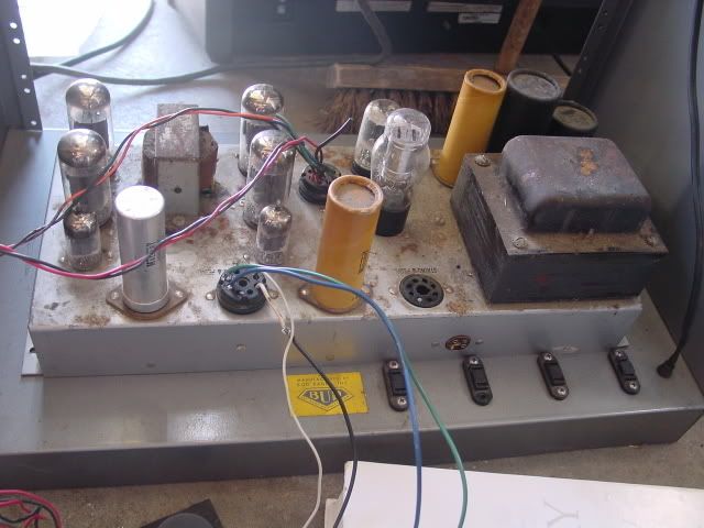
    out of a broken conn organ (rats had chewed a lot of cables and other unknown faults) and I have connected a jack to it so I can play it with a guitar or piano, etc. It sounds great right now, got it sounding out of the small leslie that came with it and 2 12" drivers that were in the organ as well, but I have no tone, volume controls or a standby switch.
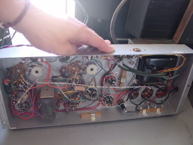

    I've heard you place the standby switch between the plates and transformer, and tone between stages of gain. If this is true, where are the plates and the gain stages in this amp?


    The pots you see in this above photo control the left and right channels of the speakers. They are cranked right now but it is not very loud. I wish to get this thing breaking up if I can.

    I have a volume pedal as well and may end up using it solely for this amp, but f I wanted to wire controls in it, where would they go?

    I plan on making a boost pedal that I would install on board or keep it on the floor, any suggestions about either idea?

    Thanks for any help you'all could'n give'n me.
    Last edited by daviddec; 09-05-2006, 11:13 AM. Reason: new info

  • #2
    OK, it doesn't have volume and tone controls because it is just a power amp, there is no preamp there. That is also why it is not very loud. You'd need a peramp for any tone and volume controls as well as overdrive of any kind. There are no gain stages.

    Is that coke bottle tube a 2050? If so it is a tube version of a triac, and would have been used to turn the leslie motor on and off.

    The amp survived all these years without a standby switch, I don't know why it needs one now.

    What are the four output tubes? 7868 maybe?

    I can't make it out in the picture, what went in the empty socket?
    Education is what you're left with after you have forgotten what you have learned.

    Comment


    • #3
      I see enzo, would it be easy to make a preamp? and/or I might have the original for it, i'll post pics tommorrow.

      the empty socket input says strings and flute and it used to come from the different sounds of the organ. The other sockets are the input socket (blue,green,black,white cables coming out) and the speaker output (to a crossover and then the speakers)

      I don't know off the top of my head the #s on the tubes, ill get back to you on that.

      And the leslie functions fine without the amp. It is two switches that were mounted on the top dash on/off and slow/fast. I've made a stompbox that controls them.

      ummm I'll get back to this later.

      Comment


      • #4
        If the leslie is controlled without the amp, then I doubt the 2050 theory.

        I wouldn't hink the orfan had a preamp per se, but there may be other circuits in there you could make into a preamp. Or just use some pre-existing preamp.

        Yeah, I figured out the speaker and input sockets.

        Let us know the tube complement. The two power amps on the left and the smalle tube next to each is the phase splitter for it. DOn't know what the tubes on the right do. COUld be useful for making a preamp circuit.
        Education is what you're left with after you have forgotten what you have learned.

        Comment


        • #5
          Ok so heres the low down


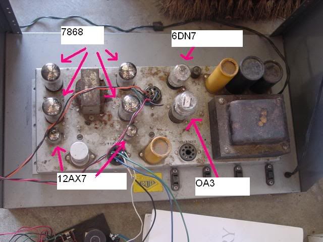
          as you can see there is 8 tubes all labeled.

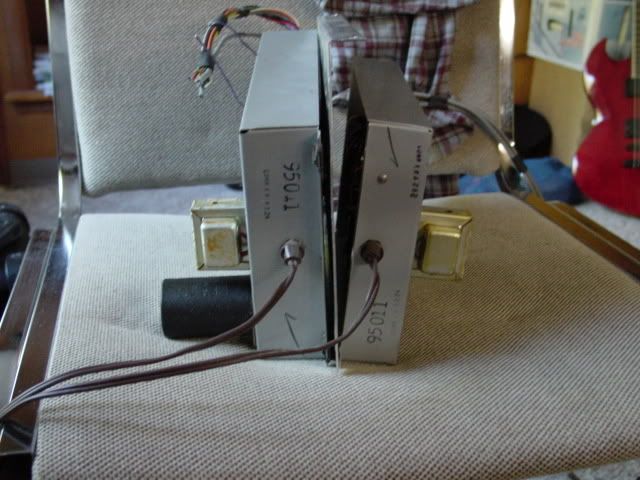
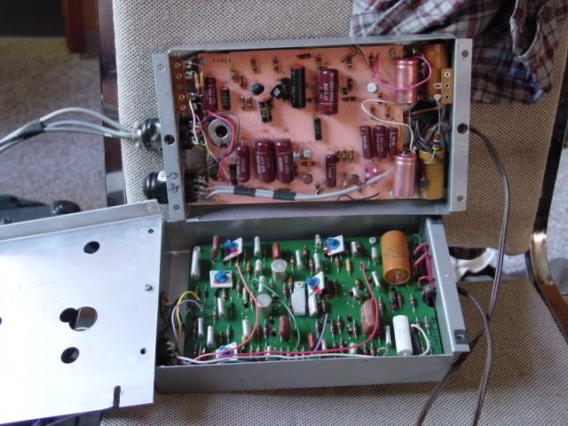
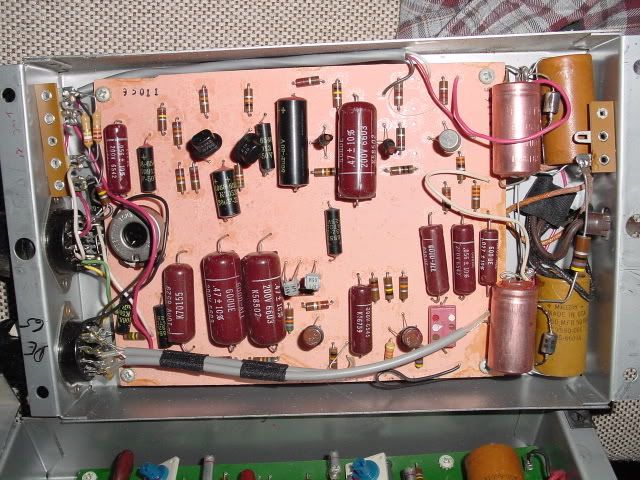
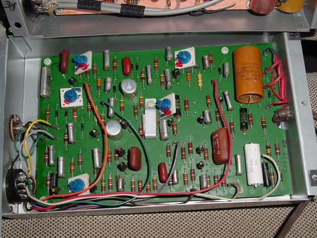
          here are some shots of what I believe is/was the preamp


          It looks like any preamp I've ever seen on a tube amp, but I don't know which cable coming out of it does what.

          Anybody out there who has any idea....

          Comment


          • #6
            Oh cool, those are 7868 then, and the 12AX7s are the phase splitters. Two very basic power amps, and looking at the two output transformers I'd guess maybe 20 watts tops.

            The 0A2 is a voltage regulator tube - 150 volts in this case. Think of it as a tube version of a zener.

            The 6DN7 has the same base as the 6SN7 - a dual triode. Can't tell by looking what it is there for. Possibly part of a voltage regulation circuit or maybe something else. Maybe someone else has an idea.

            The extra modules aer solid state circuits, and each appears to have its own internal power supply with a mains cord trailing out. Beyond that, who knows. With all the adjusters on it, the lower one could be something. There are not enough of them for it to be the top octave divider, but it might be a mixer for the various voice sections. The RCA jack on the left makes me think auio though. Not sure what, possibly a reverb return. Or drive.

            The upper one could be anything. The two shielded cables along the lower edge look like audio, but... could be a line output driver I guess. What does the lavel say on the jumper plug plugged into the left end of it?

            Is there any writing on the ends or cover?
            Education is what you're left with after you have forgotten what you have learned.

            Comment


            • #7
              Answers

              Hi, Ok what you have there my friend is a power amplifer from an old Conn Hibrid organ (Valves & Transistors) The OA3 Regulator tube stablised a 75 volt supply for the tremolo generator which is on another chassis. the 6DN7 formed a regulator in conjunction with the OA3 to supply blocking voltages for the flute keying circuits on printed boards.
              The Amplifer its self is two channel. 20W RMS per channel at the onset of clipping. If you intend using this for a guitar amplifer you will have to provide a preamp. There are peramps in the organ but they wont be suitable for a guitar as the gain is not sufficent. They were germanium transistor preamps anyway. You will have to build a preamp in the in the power amp chassis. You can get rid of the OA3 & 6DN7 that will give you room to build the preamp. To use both 20W amps you can wire them both up to the preamp . Tone controls can also be incorperated. If you woud like a schematic for the amp I can scan you one from Conn service manuals I have here.
              Contact me with e-mail at bscott2@optusnet.com.au and I can send them to you.
              I repair vintage organs, have done for many years. I am a qualified electronics tech and collect & refurbish vintage organs now for a hobby.
              I don't know your level of experience or age but Valve gear isn't hard to work on. Whilst I was serving my apprenticeship in this trade I used to design Tube guitar amplifers and hand wind the required transformers (output and power) I was poor back in mid sixties when I started in the electronics industry, Electron tubes were king then and I worked on many tube amplifers, guitar and PA amps.

              Regards Robert


              Originally posted by daviddec View Post
              Ok so heres the low down


              as you can see there is 8 tubes all labeled.

              here are some shots of what I believe is/was the preamp


              It looks like any preamp I've ever seen on a tube amp, but I don't know which cable coming out of it does what.

              Anybody out there who has any idea....

              Comment


              • #8
                Suh-weeet!

                Those transistors and inductors are beggin' to be used in fuzz-faces, wahs, and rangemasters. The non-dipped foil caps look like the ones used in the 70's cry-baby's. To the vintage electronic experimenter, old organs are what the Buffalo was to the Indians - strip it and use every part. .....um..except the E-lytics, which naturally go to the great circuit in the sky.

                Comment


                • #9
                  where to start?

                  I have this exact amp still sitting in an old Conn organ in the garage; I would love to turn it into a guitar amp, but I don't know... anything. How do I plug in my guitar, how do I build a pre-amp. Where do I start? Your magnanimity will be greatly appreciated.

                  Comment


                  • #10
                    Current Status

                    Ok, so its been a while since I did anything with this post. Sorry bout that. Here's what I ended up doing to this organ amp.

                    I cut down the size of the wood that housed the entire organ, and reconstructed a unit that houses just the rotating speaker and the tube amp itself. So it used to be 5 feet wide and I cut it down to 2.5 or so (see photos). I wanted to wire up the old volume pedal as a foot controller for the speed of the leslie motor, but (see that conversation here http://www.diystompboxes.com/smfforu...4504#msg354504 it couldn't work, so I ended up constructing a foot switch that would turn the leslie on or off and go fast or slow.

                    I didn't and still don't understand how the preamp would work so I went and bought a cheap tube preamp that I had the signal go through just before this amp.

                    I ended up using some of the capacitors in the organ's preamp and wired them into my dunlop crybaby pedal. Really good idea; I still have the preamp as a vintage part collection with the intention to use more parts.

                    that's about it! I like to use this with my yamaha organ or when I feel like tearing my guitar through the leslie.


                    Comment


                    • #11
                      I recently disassembled the same Conn organ and kept the speakers and the power amp. A schematic of the power amp would be most helpful. Please let me know how I may acquire one and the cost. Thanks.

                      Comment


                      • #12
                        I am working on the same power amp and am drawing a schematic as I go.I am making a stand alone Leslie and plan on gutting the regulator circuit and using a 6SQ7 and 6SN7 for a pre amp in the octal sockets from the regulator circuit.Will post the schematic when I am done.I have the power section completed I just need to double check it before I post it.

                        So far I have learned,from my friends on the amp garage forum,that this amp uses a phase inverter like the old Fenders and Supros.Its called a paraphrase inverter.More info on it here. The Valve Wizard -Paraphase

                        Oh yeah,first post,hello all.

                        Comment


                        • #13
                          I have been given a non-working 1961 Conn Minuet model 541. I would like to remove the entire amplification section (which appears to be identical to the one above) for use as an experimental guitar amp. Below is a link to my blog dedicated to this "repurposing" hobby.
                          DIY Guitar & Amp

                          Would someone aid my effort by sending the schematic and/or wiring diagram for this organ or one similar?

                          Comment


                          • #14
                            David what are the 4 wires going into the conn tube amp from your pre-amp? are you splitting the signal?

                            CBraet


                            Originally posted by daviddec View Post
                            I pulled this old tube amp

                            out of a broken conn organ (rats had chewed a lot of cables and other unknown faults) and I have connected a jack to it so I can play it with a guitar or piano, etc. It sounds great right now, got it sounding out of the small leslie that came with it and 2 12" drivers that were in the organ as well, but I have no tone, volume controls or a standby switch.


                            I've heard you place the standby switch between the plates and transformer, and tone between stages of gain. If this is true, where are the plates and the gain stages in this amp?


                            The pots you see in this above photo control the left and right channels of the speakers. They are cranked right now but it is not very loud. I wish to get this thing breaking up if I can.

                            I have a volume pedal as well and may end up using it solely for this amp, but f I wanted to wire controls in it, where would they go?

                            I plan on making a boost pedal that I would install on board or keep it on the floor, any suggestions about either idea?

                            Thanks for any help you'all could'n give'n me.
                            Comment

                            Working...
                            X