 Tweet
Tweet
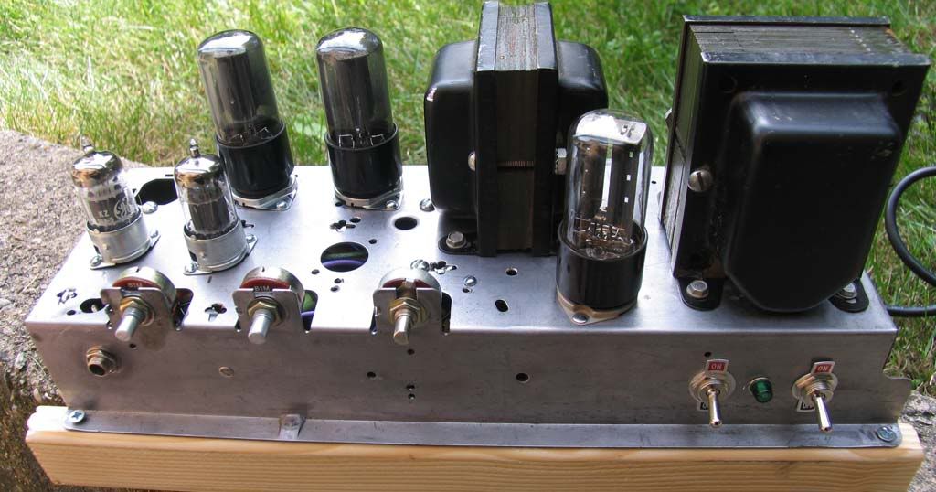
My first build (yea... probably should have been a kit)... have learned a ton... but am stuck.
The chassis and transformers came to me build... but sloppy and not my thing so I decided to start from scratch with a new board and new tube sockets.
Its a clone of a spitfire but with 6V6's. I did mod some components to accommodate the 6V6's. I also mounted the board 180 degrees from what makes sense... but will fix that later. And the line out has been disconnected for trouble shooting.
I have 5 volts on pin 4/5 of the 6V6. It powers up and all tubes light... but I get no sound. I have swapped out all tubes for known working ones. And have been over the schematic and layout a dozen times. Not sure what to do next. Any help (and critique) would be very much appreciated.
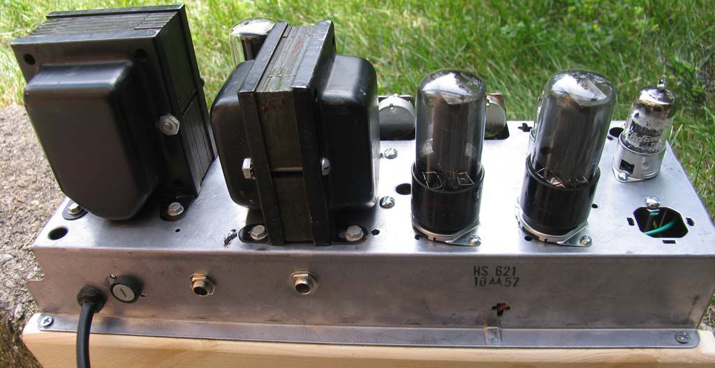
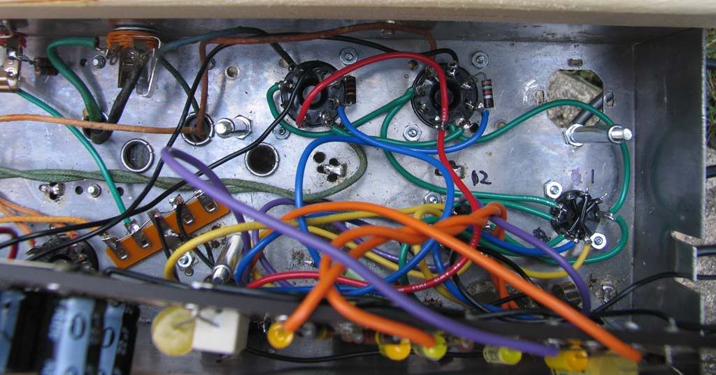
top layouts
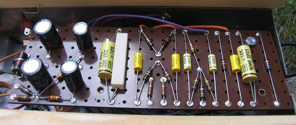
main board
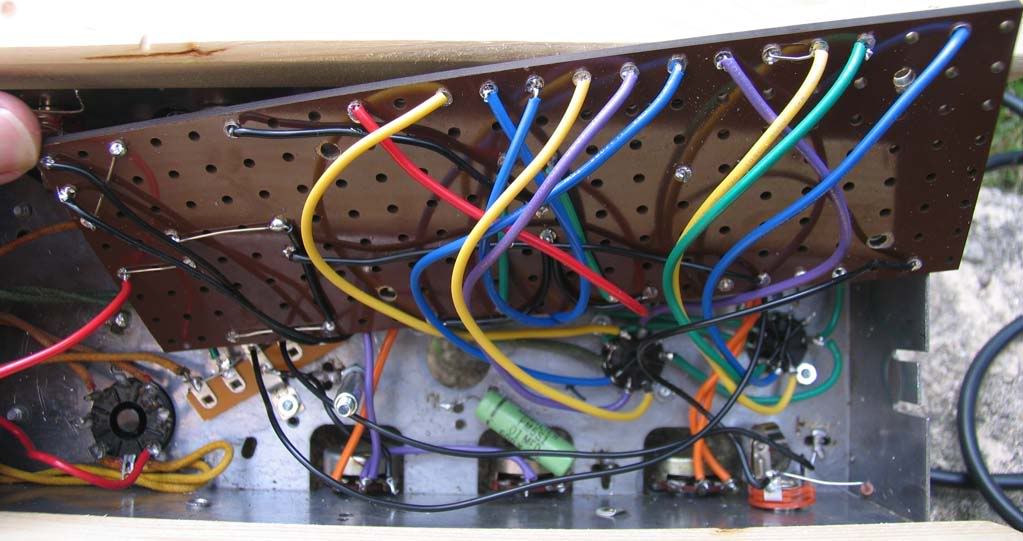
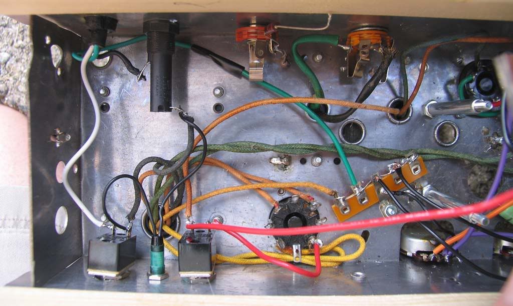
Chassis wiring
thanks for any insights in advance...
Mark
The chassis and transformers came to me build... but sloppy and not my thing so I decided to start from scratch with a new board and new tube sockets.
Its a clone of a spitfire but with 6V6's. I did mod some components to accommodate the 6V6's. I also mounted the board 180 degrees from what makes sense... but will fix that later. And the line out has been disconnected for trouble shooting.
I have 5 volts on pin 4/5 of the 6V6. It powers up and all tubes light... but I get no sound. I have swapped out all tubes for known working ones. And have been over the schematic and layout a dozen times. Not sure what to do next. Any help (and critique) would be very much appreciated.
top layouts
main board
Chassis wiring
thanks for any insights in advance...
Mark
Comment