Ad Widget

Collapse

Announcement

Collapse
No announcement yet.

5F1 - hum and speaker crackle

Collapse
X
 
  • Filter
  • Time
  • Show
Clear All
new posts

  • #31
    You aren't using isolating jacks are you? The pot buss & wire from V1 pin 3 cathode can just connect to the ground lug of jack #2. You don't really want an additional ground lug there. Where is your 1M input load resistor for the high gain input, as drawn you just have 2x68K dropping resistors in series between input jacks & tube grid, with no load resistor to ground.

    Really, the 220K 6V6 grid load & 6V6 cathode resistor should ground with the PT CT & main filter but you might get away with grounding them (along with preamp filter cap) at Jack #2 also. Sort the input first - many 5f1 have these components (220K/470ohm/pin8 cathode) grounded like your amp...look at it again if you need to later.
    Comment


    • #32
      MWJB

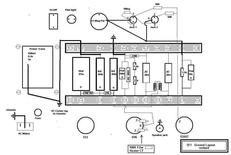
      Have a look at my diagram again , I made some errors. added in the 1 meg load resistor to the diagram layout, at the input jack. The pot ground is also corrected. The heater ground from pin 8 6v6 to elevated ground point at the cathode resistor and coupling cap, positive side. These omissions from the diagram were in the actual build so I know this should not be a problem area.

      thanks for the reply , you probably saved me from tossing this POS in the trash just now.
      Also, I completely ripped the entire build apart down to every single component. I plan
      to either rebuild it again if I have any patience left or toss it in the trash can. It probably would
      have hit the trash can if I did not have any replies to my last post, but I'm trying to hang on, however
      my morale is at a all time low right now. If I can only rid this oscillation problem , it has ruined the whole project.

      Here is the corrected diagram, the actual build as it stood a hour ago. Its now stripped down to a pile
      of parts. Maybe I'll get a second chance to get this right , I 'd hate to loose my $300 investment to
      a pile of electronic rubbish.

      Hands down, This project has to be the worst case of bad amp voodoo I have ever experienced.


      Last edited by electrochronic; 12-11-2009, 09:29 AM.

      Comment


      • #33
        "Also, I completely ripped the entire build apart down to every single component. I plan
        to either rebuild it again if I have any patience left or toss it in the trash can." Stop trying to force the traditional 5F1 layout into your tiny chassis...rewire it point to point, there appears to be short enough distances between connections in the amp.

        The ONLY ground point for the preamp/pot buss will be your input jack ground - ground 12AX7 cathodes, preamp filter cap here (mount the "-" of the preamp filter directly to the jack ground, the "+£ to the junctionm of the 100K plate resistors. Ground everything else to a PT bolt, using a single wire for each component, AC cord gets its own ground.

        Your terminal strip looks like it has screw connections, components are (were) soldered aren't they?

        Comment


        • #34
          Yes soldered P to P. The terminal strip was made for both scew connections and PCB mounting. I bent the PCB pins inward so I could solder the components to it p to p. The screws are just there to secure each of the pin plates to the plastic strip. Yes, true the area is really tight but, I built it in such a way that I can pull the terminal strips out with all the components attached as one assembly. I do have to de-solder all the wired connections to the tube sockets in order to release the whole assembly as one

          In a earlier version of grounding layout , I made a ground connection between the pot , #1 input jack ground , and a ground bus that ran from right to left starting at the preamp side ground, all neg side of caps and eventaully working over toward the PT CT. I noted no difference in the amp nearly non existent hum or buzz at full volume idling no guitar plugged in the the #1 jack. Now if I plug the Telecaster into the amp I get the usual single coil pickup noise which has nothing to do with the amp.

          In all my ground iterations the amp remained very quiet. However , in every case the oscillation continued to haunt this amp, unrelenting.

          The IEC safety ground continues to have its own ground in each revision.

          Either I'm missing a major ground issue here which can be attributed to the oscillation or my chassis and base design is just the underlying problem.

          Usually when the amp is quiet at full volume , you would think that the project is finished ( all grounds good) , but as soon as I hit that low string on the telecaster at high gain ( guitar volume pot all the way up and amp 3/4 to full volume) that oscillation just reduces this thing to the worst guitar amp you've ever heard.
          Just kills me to hear this thing sound like this.

          I should post the oscillation sound when I get this built up again. Maybe hearing what the oscillation sounds like will help in identifying it as coming from the preamp, power supply or neither.

          When I rebuild this again, I'm hesitant to re-use my old components eventhough the all caps pass my cap checker tester using ESR and capacitance , as well as the resistors passing ohm tests. Any thoughts ?
          Last edited by electrochronic; 12-11-2009, 10:22 AM.

          Comment


          • #35
            "When I rebuild this again, I'm hesitant to re-use my old components eventhough the all caps pass my cap checker tester using ESR and capacitance , as well as the resistors passing ohm tests. Any thoughts ? " Whilst I doubt that a component (other than the speaker) is responsible for your issues, caps & resistors are cheap...if you have to buy some new parts to execute a better layout, that that's what you must do.

            Comment


            • #36
              I'd love to blame the speaker and call it a day, but I put a 8" weber , and a 12" peavey on the amp and received the same old treatment of haunting oscillation. These two test speakers are from good working amps.

              Where is the cheapest turret board blanks and pegs for the DIY amp builder, I was reading on Tubeswell using some electrical board and eyelets, but I looked around and could not locate a local source. The reason I used term strips was due to low cost and local sourcing.

              I don't want to layout a lot of cash in my situation. I'm already taking a beating.

              One additional note, How do I know my OT transformer is any good ?

              maybe I should run a square wave thru it and watch my scope , does any one have a procedure
              for this, a passive test , out of circuit. None of my lousy guitar amp books tells me how this should be done.
              Last edited by electrochronic; 12-11-2009, 10:56 AM.

              Comment


              • #37
                Just use a few terminal posts/strips - see my post on the subject on Caner's thread re. his "5F2A low bad noise"...most of your components can be fitted from tube socket pin to next tube socket pin/ground/pot as necessary...you probably only need somewhere to mount the 100K plate resistors, preamp filter & 22K power supply dropping resistor.

                PM me if you want me to e-mail you a sketch of what I mean.

                Comment


                • #38
                  Just got off the phone with a very knowledgable analog design engineer who said I am using the wrong output transformer that was not designed to run as a single ended OT. He explained that the DC saturation in the trasnformer core and high feedback are the cause of the oscillation. Its a regenerative cycle that makes the amp become a oscillator everytime I hit a low note. Increases gain which activates the high saturation or oscillation.

                  So my layout and grounding are not the root cause , as I suspected. I'm going to get a proper single ended OT and report back.

                  I thought something was suspicious after I rebuilt the amp several times with no changes. The only constant in all of the re-build attempts were the OUTPUT TRANNY.

                  The Hammond 125 C - push pull only( 2x6v6 ), not suitable for single ended 5F1 design.

                  I should be using the Hammond 125 "SE" series (1x6V6) transformers "single ended"
                  Last edited by electrochronic; 12-12-2009, 07:18 PM.

                  Comment


                  • #39
                    Hi Electrochronic

                    I think having the ground return of the pre-amp filter cap tied to the other filter caps ground returns may cause oscillation, esp. as power/signal is increased.

                    The reason is that the ground returns of the other filter caps and the ground return of the 6V6 cathode resistor will have bigger micro-rises in ground potential as the signal gets stronger, and this could feed back into the ground return path of the pre-amp filter cap, and thence into the plates of the pre-amp stages.

                    I can't recall whether you tried taking this pre-amp filter cap ground return to a different point, but I recommend that you run a separate wire from this point to the input socket ground instead. (Sorry if this aspect has been debated previously)
                    Building a better world (one tube amp at a time)

                    "I have never had to invoke a formula to fight oscillation in a guitar amp."- Enzo

                    Comment


                    • #40
                      Tubeswell,

                      no , problem

                      I don't think I posted a grounding scheme like the one you describe, I have tried so many up to this point.
                      I do recall performing this scheme on the bench ,but it seemingly made little difference as I can recall.

                      I'm pretty confident that using my current transformer is the root cause. I will have a chance to prove that when I get my mitts on a correct OT.
                      Last edited by electrochronic; 12-11-2009, 10:46 PM.

                      Comment


                      • #41
                        I agree that it looks wrong if things are wired the way shown in the previous page. The DC and AC returns of the power tube cross with the preamp filter as TW mentions.

                        Comment


                        • #42
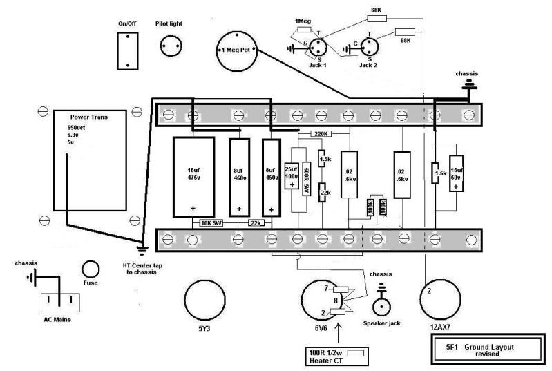
                          Does this represent Tubeswell's grounding recommendation ?

                          changes made, have a look, I tried the schem below with no change in oscillation.

                          Comment


                          • #43
                            it's still wrong (same reason)

                            Comment


                            • #44
                              Hi electrochronic. I recommend separate wires from each ground return point to either one of the two main grounding points. If you try and combine some of them as shown in your diagram, you will increase the probability of getting different ground potentials (- what I meant when I said microrises -) in the ground return.
                              Building a better world (one tube amp at a time)

                              "I have never had to invoke a formula to fight oscillation in a guitar amp."- Enzo

                              Comment


                              • #45
                                Tubeswell,

                                Maybe you can indicate where the error is in the schematic above. I'm having a difficult time decifering your references to the two main grounds. Specifically at what points ?

                                My understanding is that the two main grounds are at PT CT and line safety
                                ground. Also my understanding is that all grounds should terminate at PT CT.

                                Is this correct ? If not where do changes need to be made, need more specific detail.

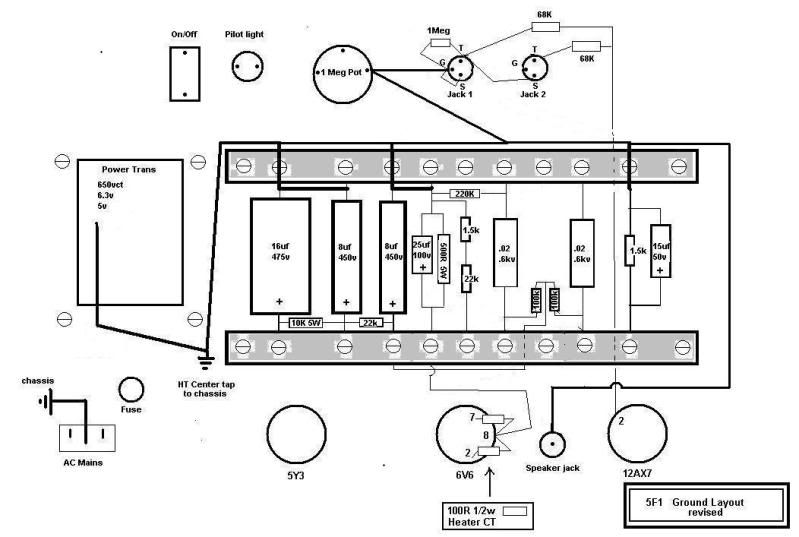
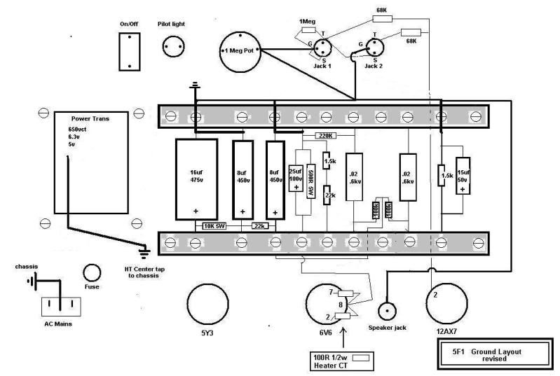
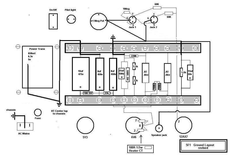
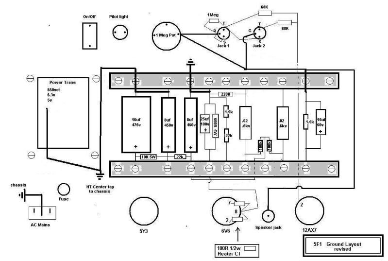
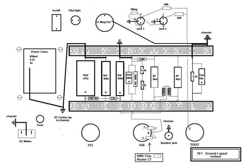
                                Here is another series of ground layouts maybe this is what your talking about , If not indicate specific errors.


                                Here is another version


                                and another version


                                and another version


                                and another version


                                Thats 5 new versions, Maybe one of these will come close, I have many more versions , if not.
                                Last edited by electrochronic; 12-13-2009, 10:51 PM.

                                Comment

                                Working...
                                X