Ad Widget

Collapse

Announcement

Collapse
No announcement yet.

More 5F1 Champ Build problems...this one is strange

Collapse
X
 
  • Filter
  • Time
  • Show
Clear All
new posts

  • More 5F1 Champ Build problems...this one is strange

    Hi everyone. Trying my hand at building a Marsh-Mojo 5F1 Champ. I'm trying to diagnose what I've screwed up or see if I've got a faulty component.

    The first time I powered up the amp there was a very loud hum that wasn't affected by the volume control. I plugged in a guitar cable and got nothing. When I pulled the cable out the 25uF 25V capacitor exploded.

    One look at the capacitor revealed that I had installed it with the wrong polarity. So, I installed another one with the correct polarity and the same thing happened; Loud Hum not affected by volume control and exploding capacitor when removing guitar cable.

    At this point I took everything apart and rebuilt the board and chassis trying to be as careful as possible.

    More information: All the tubes light up. The amp fuse hasn't blown. When I place a guitar cable into the input jack it makes no static on insertion or while it's installed but blows up the 25uF capacitor when removed.

    This seems so simple to diagnose. Thanks in advance for any insight!
  • #2
    "More information: All the tubes light up. The amp fuse hasn't blown. When I place a guitar cable into the input jack it makes no static on insertion or while it's installed but blows up the 25uF capacitor when removed." Hmmm, which 25/25 cap? Is this the power tube cap, or the 12AX7 cap? Are you sure that the cap blowing when you pull out the guitar isn't just coincidence.

    If the 12AX7 - check that this cap and the 1500 resistor in parallel are actually connected to pins 3 & 8 (joined). Rather than accidentally hooked up to the high dc voltage on pins 1 & 6.

    If the 6V6 cap, try a new 6V6 & triple check that you have connected everything to the right socket pins, this cap and the 470R resistor connect to pin 8. Don't keep refitting 25v caps, use a 50-100v cap next time (though I wouldn't expect a 25v cap to blow that quick). If the amp is humming loudly the voltage on the 25/25 cap will rise under signal...it's probably around the 25v mark at idle anyway.

    Have you tried reversing the blue & red wires from the OT?

    Comment


    • #3
      Thanks for the reply MWJB!

      I tried reversing blue/red from the OT and there was no change. Each time that the 25uF cap exploded I had a clear view of the inside of the chassis and it happened about halfway through the removal of the 1/4 jack. I've looked at both jacks to see if there is a wire touching where it shouldn't and they both look clean.

      The cap I'm referring connects directly to the 8 pin on the 6V6. (I've installed a 25uF 50W cap) I don't have another 6V6 to try but I'll order one in.

      On the three 5F1 layouts I have the only joined pins on the 12AX7 are 4&5. Pin 3 goes to 1.5K resistor then ground. Pin 8 connects with the 22k and 1.5k resistors.

      I also tried reversing the filament wires between the pilot light and 6V6. As expected, not much change from that.

      Thanks again for your help!

      Comment


      • #4
        "On the three 5F1 layouts I have the only joined pins on the 12AX7 are 4&5. Pin 3 goes to 1.5K resistor then ground. Pin 8 connects with the 22k and 1.5k resistors." Aha! You're quite right, I was thinking 2 channel amp when I wrote that, doh!

        Your input jacks do not connect directly to the 6V6 in any way, it is pretty well impossible for removing the guitar to be causing the cap to fail, if the closed jack caused it to fail, it would do so with nothing plugged in.

        Reversing the heater wires from pilot to 6V6 would not do anything, the amp is single ended so the power section does not cancel hum like a push-pull output. Confim that you have 2x100ohm virtual centre tap resistors, one going from each leg of the heater winding to ground, with no other ground reference/centre tap etc? Your reference to "3 layouts" is a bit of a worry...mixing & matching regarding the heater wiring can be a cause for issues.

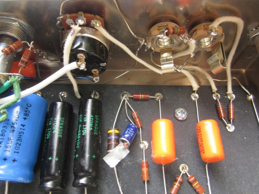
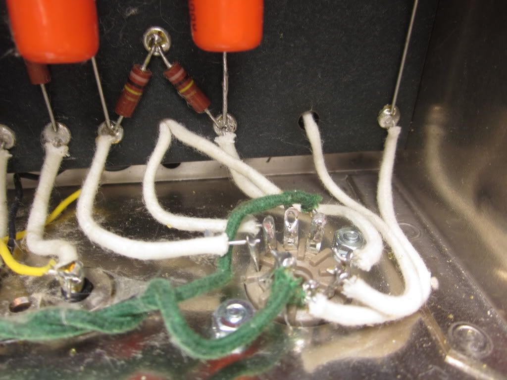
        Can you post some pics showing circuit board & tube socket wiring.

        Comment


        • #5
          [IMG][IMG][IMG][/IMG][/IMG][/IMG]Here are some pics. I can post more if needed.
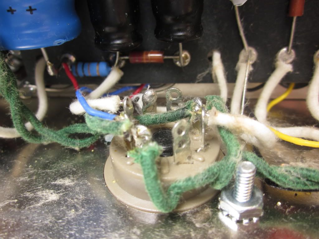
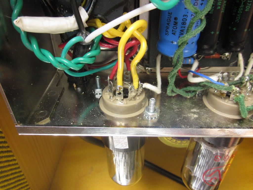
          Thanks
          Last edited by Lightning13; 06-01-2011, 09:50 PM. Reason: picture links

          Comment


          • #6
            More pics

            Comment


            • #7

              Comment


              • #8

                Comment


                • #9
                  A note on the exploding cap. It explodes as the cable (that's not connected to a guitar) is pulled out. It is ok with a cable all the win or completely out. But, somehow in the process of pulling out the cable it goes pow. The blue cap in the picture was pretty messy to clean up after.

                  Comment


                  • #10
                    Are your inputs hooked up correctly? It looks like you might have the 1m resistor going to the "switch", and then ground? I could be wrong, because it is hard to look at pictures vs. real life. Have a look at this from Hoffman amps...

                    Also, what is that cap tucked under the pot/switch? Is that a line-to-ground cap? If so, that is a "feature" of the orginal that you don't want to emulate. We don't do that with modern wiring.
                    Attached Files

                    Comment


                    • #11
                      JHow, What you see under the pot is the ground wire that goes around the chassis. It's not connected directly to the pot.

                      Those inputs have been driving me nuts. I've seen diagrams how I've got mine set up and like the hoffman picture. I'll try it again the hoffman way.


                      More Info: I tried another 6V6 tube and got a very loud microphonic squeal just when the tubes warmed up. I then changed the reversed OT blue/red wires reversed from a previous soldering session and the squeal went away.

                      So, wiring is back like it should be, new 6V6, and still have the Hum with no sound.

                      I'll change the input jacks this evening.

                      Comment


                      • #12
                        Originally posted by Lightning13 View Post
                        Those inputs have been driving me nuts. I've seen diagrams how I've got mine set up and like the hoffman picture. I'll try it again the hoffman way.
                        As JHow pointed out, the 1meg resistor appears to be hooked up incorrectly. It should add 1meg resistance from ground to tip, and then jump the shunt tab (first attachment), whereas yours appears to add the resistance from the tip to shunt (second attachment).
                        Attached Files
                        My Builds:
                        5E3 Deluxe Build
                        5F1 Champ Build
                        6G15 Reverb Unit Build

                        Comment


                        • #13
                          Originally posted by Lightning13 View Post
                          JHow, What you see under the pot is the ground wire that goes around the chassis...
                          We'll your picture in post #8 seemed to show an "orange-drop" hanging out between and below the pot and the pilot light - in the upper left part of the picture. That was what I was asking about. It suggested to me that you might have a cap from line to chassis - like the orginal amps.

                          The "hoffman" jack scheme will work. You can leave the 68K resistors on the board or put them on the jacks like hoffman shows. Sometimes I do the latter and use sheilded wire (ground only one end of shield) to go straight to the grid on the 12ax7. I sometimes also use shielded wire from the volume pot the grid on the second stage as well - to reduce noise.

                          Comment


                          • #14
                            Maybe completely wrong guesses...

                            Since it's blowing the output tube cap, have you checked the speaker and transformer connections to the speaker? Makes me think of some of the nastiness you can get from not having a speaker attached to the output transformer....just a thought....double-check the resistors on that 6V6 and make sure they haven't been blown open or short.

                            Comment


                            • #15
                              Ok, I tried wiring the jacks the, I hope, correct way aka JHow's suggestion. It's not humming nearly as loud as it has which is good. Since i got the microphonic type squeal out of the speaker I'm thinking it's hooked up correctly:

                              From the output of the mercury transformer I have the yellow going to the center pin of the RCA jack and the Black going to the ground ring. Me thinks thats the way it's done.

                              The resistors all seem to be in good shape.

                              Could the rectifier tube be causing problems like this? The hum goes away when the 6V6 and 12ax7 are out. I was able to swap those tubes earlier with no affect to hum or output.

                              Oh, there is the original style orange drop running from the fuse to ground. I've taken this out of the circuit with no effect.

                              Thanks for all the ideas! Please keep them coming.

                              "Geez, I thought this thing was only going to take a couple days...." - wife

                              Comment

                              Working...
                              X