Ad Widget

Collapse

Announcement

Collapse
No announcement yet.

5B6 build issues

Collapse
X
 
  • Filter
  • Time
  • Show
Clear All
new posts

  • #16
    Here's the schematic, should be a workable link: http://zhyla.net:4000/files/dev/bass...m_modified.jpg

    Ok, I recapped with 3 brand new 33 uF caps. No change. I was expecting this but it was good to remove all doubt.

    On the 6SC7 the grid pins and plates are close together (it goes plate 2, grid 2, grid 1, plate 1). I haven't shielded the grid wires. I think I have some shielded cable around here somewhere. But given that the noise persists when the preamp tube is pulled I don't think this is my problem.

    What did you think of my replies above to Enzo's questions? It sounds like the phase inverter stage is where the problem is. Do you agree? The last plate and cathode voltages I measured are below, in case that helps. The phase inverter stage is the one I understand the least.

    phase inverter plate, V2a 43.8
    phase inverter plate, V2b 45.2
    phase inverter cathode, V2a 0.905
    phase inverter cathode, V2b 0.87

    Maybe both my 6SL7GT tubes are bad and just noisy?
    Check out my signal generator for your iPhone or iPod Touch.

    Comment


    • #17
      "Page can't be displayed" re. the schem.

      Don't bother with 33uf at the main B+, go straight in at 50uf.

      Your voltages are low, what is the B+ voltage feeding the PI plate resistors. Fix this first, your plate voltages should be a little over half of the B+ supply voltage...something looks wrong here.

      Ground out the first PI triode's grid (from volume pot), does the hum change? Check routing of tap wire to PI 2nd triode's grid, keep it away from the plate wires. Check you have oriented the PI tube the same way as the schem, signal from preamp comes in on pin 4, tapped output from PI 1st stage comes in on pin 1 - 6SL7 can be noise sensitive depending on orientation.

      PI is very simple, signal goes in on the first triode's grid, comes out on the plate. A proportion is tapped off between grid load resistor & ground then fed back into the 2nd triode of the PI to provide signal for the out of phase power tube. It's called a paraphase PI, the version you have built is the non-balancing kind, they can be very fussy with regard to the value of that 6.8K - I'd fit a 10K trimmer and tune by ear.

      Comment


      • #18
        His link works for me.
        Education is what you're left with after you have forgotten what you have learned.

        Comment


        • #19
          Schematic... I've placed it on my "real" web server, maybe this will work for MWJB: http://audioartillery.com/static/fil...m_modified.jpg

          Anyways, I had the cathode connections swapped on the PI tube. I don't understand how it would work the other way but it doesn't sound noticeably different with it fixed. Regarding the orientation, I happen to have it connected as MWJB described. I didn't realize this was important - the 1st triode is always the top one?

          With the 1st grid grounded the hum persists but obviously does not scale with the volume pot.

          The relevant voltages are below. The PI plates are nowhere near half the B+3, obviously. I was targeting 400 V for B+1 but overshot in knocking down the voltage by 50 V; correct zener is coming tomorrow. I can't see how that would magically bring the PI plates from 40 V to 150 V though.

          Code:
          preamp plate, V1a/V1b          	84.6
          preamp cathode           	1.25
          phase inverter plate, V2a	41.7
          phase inverter plate, V2b	43
          phase inverter cathode, V2a	0.87
          phase inverter cathode, V2b	0.82
          power amp plate, V3     	339
          power amp plate, V4     	339
          power amp cathode, V3/V4	21.9
          power amp screen, V3/V4      	305
          B+1	348
          B+2	305
          B+3	295
          Regarding tuning the 6.8kOhm resistor. Which one are you referring to, R14 (which connects to PI grid 2)? What would I tune for? Lack of hum?
          Check out my signal generator for your iPhone or iPod Touch.

          Comment


          • #20
            "Regarding tuning the 6.8kOhm resistor. Which one are you referring to, R14 (which connects to PI grid 2)? What would I tune for? Lack of hum?" Yes, R14 would be tuned to provide good fidelity (within reason for the design anyway), not hum. But this isn't the immediate problem...

            It's possible that R15 is too high a value (remove it from the circuit & check value), or that R3, R5, R6 are too low. What values did you use for the preamp & PI cathodes, you don't often see 2500ohm or 5000ohm resistors these days?

            A picture of the chassis would be useful.

            Comment


            • #21
              Originally posted by MWJB View Post
              "Regarding tuning the 6.8kOhm resistor. Which one are you referring to, R14 (which connects to PI grid 2)? What would I tune for? Lack of hum?" Yes, R14 would be tuned to provide good fidelity (within reason for the design anyway), not hum. But this isn't the immediate problem...

              It's possible that R15 is too high a value (remove it from the circuit & check value), or that R3, R5, R6 are too low. What values did you use for the preamp & PI cathodes, you don't often see 2500ohm or 5000ohm resistors these days?

              A picture of the chassis would be useful.
              Checked R15, it's 9.82 kOhm. R3 is a 2.5 kOhm but for R5 and R6 I could only find 5.1 kOhm (they checked at 5.06 kOhm before I installed them). I also checked R13 (if it was really high V2a wouldn't sink as much current), it's dead on.

              A couple big shots of the chassis as of this morning:

              http://audioartillery.com/static/fil...p/IMG_5461.JPG
              http://audioartillery.com/static/fil...p/IMG_5462.JPG

              From left to right, V4, V3, V2, V1. The heater wires for V1 I originally had running against the chassis wall but recently moved it to the middle section to get it away from the preamp grids/plates. Didn't make a difference, I'll probably move it back.
              Check out my signal generator for your iPhone or iPod Touch.

              Comment


              • #22
                You have miswired one of your 250K plate resistors, all three should fork out from the junction of the 10K power supply resistor & preamp filter cap - one of yours is in series with the plate resistors for the PI tube and is dropping too much voltage.

                Comment


                • #23
                  remount 6L6 grid load resistors (R9 & R10) & r14 physically between the PI tube & the power tubes, you don't want that long grid wire from V4 back to V2's 2nd grid. You want parts to actually fall in the order they are in the circuit.

                  Ground preamp filter cap to input jack ground, not to buss. Preamp cathodes should be grounded here too.

                  Get rid of that 33uf main filter, 50uf here.

                  Basically i would rethink grounding and run a buss wire from input jack ground accross the pots for preamp & pi grounds, main filter & screen filter, 6L6 cathodes all grounded direct to a PT bolt with any centre taps.

                  You could spend weeks chasing down hum with this current layout.

                  Comment


                  • #24
                    Well goodness I've made a lot of wiring mistakes so far. Can you tell I write software for a living yet? I really appreciate the help.

                    New voltages. Do they look sane?

                    Code:
                    preamp plate, V1a/V1b   	119
                    preamp cathode          	1.67
                    phase inverter plate, V2a	164
                    phase inverter plate, V2b	164
                    phase inverter cathode, V2a	2.44
                    phase inverter cathode, V2b	2.44
                    power amp plate, V3           	347
                    power amp plate, V4            	347
                    power amp cathode, V3/V4	22.5
                    power amp screen, V3/V4        	305
                    B+1	354
                    B+2	305
                    B+3	287
                    The amp got a lot louder. The hum is still there. Also there is a lot of white noise and crackling that I usually associate with a bad tube. This noise scales with the volume and dominates over the hum.

                    My plan is, assuming the voltages above are ok, to rewire the grounding in the preamp area as you described and if the crackling persists get some new preamp and PI tubes. Actually I can't any explanation for the crackling except that the preamp tube is faulty - am I wrong here?
                    Check out my signal generator for your iPhone or iPod Touch.

                    Comment


                    • #25
                      Well, I did as you said, running a buss wire across the jacks and pots and connecting the preamp, and PI, and preamp filter cap grounds connect to that buss. The remaining ground points I left connected to the center buss (which is screwed to the chassis) and ran a wire to a PT bolt. The result was the hum got about twice as loud.

                      I found if I connect a jumper between the main/screen filter ground and the volume pot end of the buss wire that the hum would reduce to what it was. I couldn't measure a voltage differential between those nodes.

                      So, looks like grounding is probably my main issue here. What's the rationale for splitting the preamp section grounding from the power amp section grounding? Isn't that kind of asking for different ground potentials? If I had the input jacks isolated from the chassis would my original grounding be ok?
                      Check out my signal generator for your iPhone or iPod Touch.

                      Comment


                      • #26
                        Originally posted by zhyla View Post
                        So, looks like grounding is probably my main issue here. What's the rationale for splitting the preamp section grounding from the power amp section grounding? Isn't that kind of asking for different ground potentials? If I had the input jacks isolated from the chassis would my original grounding be ok?
                        The HV CT is the noisiest ground in the amp. By separating the ground of the preamp and it's filter cap, you allow the 10K resistor in the B+ line between the preamp filter and the screen filter cap to do it's job an remove the hum from the B+. The DC flowing through this resistor is very small so there is a small DC voltage between the grounds (maybe 1 or 2 mV) but no noise. Isolating the input jacks from the chassis would help but it's a pain.
                        WARNING! Musical Instrument amplifiers contain lethal voltages and can retain them even when unplugged. Refer service to qualified personnel.
                        REMEMBER: Everybody knows that smokin' ain't allowed in school !

                        Comment


                        • #27
                          "The remaining ground points I left connected to the center buss (which is screwed to the chassis) and ran a wire to a PT bolt. The result was the hum got about twice as loud." Ground points in the circuit want their own wires to the PT bolt, grind off any paint on the chassis at the PT bolt and stuff a bunch of solder tags under the PT bolt nut & run each ground individually to here.

                          Comment


                          • #28
                            Since I've got the HV center tap connected to a big power zener diode that is connected to the chassis, should I use that chassis location instead of the PT bolt or should I run a wire somehow from the zener to the PT bolt that I'm using for my main ground? Or just hope the two points don't have any current flowing between them?

                            I spent a lot of time just trying different things. The power tubes were grounded to a screw in the chassis between them. I found that if I connected them to the transformer bolt ground section the hum went down to a more normal level. I still need to move everything directly to the bolt

                            I found a bit of shielded audio cable and used that for the input wires, the proximity hum is now gone.
                            Check out my signal generator for your iPhone or iPod Touch.

                            Comment


                            • #29
                              The zener diode need not be connected to the the PT bolt you use as ground (other than through the chassis), however it should be close by.

                              Comment


                              • #30
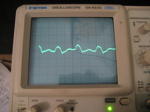
                                Armed with a cheap oscilloscope I now have more visibility into the signal chain. Here is what I see with inputs grounded.

                                At the output of the preamp what looks like a 100 Hz 10 mVpp signal with some jaggedness to it. Grounding the preamp plate doesn't make the audible noise change.

                                (larger)

                                At the V2b phase inverter plate a very complicated signal that measures 5 mVpp and I think repeated at 200 Hz. The image was taken with the preamp plate grounded.

                                (larger)

                                At the power amp plates there is this 1.5 Vpp, 200 Hz sawtooth signal. Is that my hum?

                                (larger)

                                One other thing I noticed while looking at the preamp plate (or phase inverter... I'm not sure) was that the signal would sometimes jump up 10 or 20 mV for a little while, then drop back down. The tubes were pretty well warmed up. Is this normal?
                                Check out my signal generator for your iPhone or iPod Touch.

                                Comment

                                Working...
                                X