Ad Widget

Collapse

Announcement

Collapse
No announcement yet.

AmpClones.com Mesa Boogie Mark IIC+ Help total newb

Collapse
X
 
  • Filter
  • Time
  • Show
Clear All
new posts

  • #31
    Originally posted by WesPalladini View Post
    He didn't sell me the transformer he just found somebody with a used one in the states for me.
    Sorry!
    Yes I'm a Skeptic at Heart.
    It goes with the 42 Years in the Telephony Bizz!
    B_T
    "If Hitler invaded Hell, I would make at least a favourable reference of the Devil in the House of Commons." Winston Churchill
    Terry

    Comment


    • #32
      I would recommend that you start by building several smaller electronics kits, until you develop some familiarity w/ components and soldering.
      Then after that, give the tube amp a try.

      Comment


      • #33
        PCBs and parts and video question

        Ok so here are close ups of the 3 PCBs and I made a list of parts so I can populate them. Please watch for my question: Here

        CAP BOARD
        Value Type Quantity
        220uF/350V Cap 4

        150k/2W Resistor 2

        1N4007 Diode 4

        0.047uF/1kV Cap 1

        GRAPHICS EQ

        470 Resistor 3
        1K Resistor 2

        0.033uF Cap 1
        0.15uF Cap 1
        0.22uF Cap 1
        0.39uF Cap 1
        3.3uF Cap 1

        1.0H Inductor 1
        0.39H Inductor 1
        0.22H Inductor 1
        0.068H Inductor 1
        0.033H Inductor 1

        50K Slide Pots 5

        MAIN BOARD

        Value Type Quantity
        220uF/63V Cap 2
        47uF/100v Cap 2
        470uF/16V Cap 1

        680K Resistor 2
        470K Resistor 4
        270K Resistor 2
        220K Resistor 6
        150K Resistor 3
        120K Resistor 1
        100K Resistor 1
        91K Resistor 1
        82k Resistor 2
        68K Resistor 1
        56K Resistor 1
        47K Resistor 2
        22K Resistor 4
        15K Resistor 3
        10K Resistor 2
        4K 7 Resistor 1
        3K 3 Resistor 12
        1k 5 Resistor 7
        1k 2W Resistor 3
        10M Resistor 1
        1M Resistor 2
        3M3 Resistor 1
        680 2W Resistor 1

        820 Resistor 1
        470 Resistor 5
        220 Resistor 1
        150 Resistor 3
        100 Resistor 6
        89 Resistor 1

        VALUE??? LDR 5

        10uF/63V Cap 2
        0.002uF Cap 1
        0.22uF Cap 1
        0.47uF Cap 3
        2.2uF Cap 1
        15uF Cap 4
        0.005uF Cap 2

        1nF Cap 1
        22nF Cap 2
        47nF Cap 6
        100nF Cap 5
        100nF 200V Cap 1

        10pF Cap 2
        20pF Cap 1
        47pF Cap 1
        120pF Cap 2
        250pF Cap 2
        500pF Cap 1
        750pF Cap 1
        1000pF Cap 1


        MPSA63 Darlington Transistor 1 Q1
        MPSA20 Darlington Transistor 1 Q2
        MPSA70 Darlington Transistor 1 Q3
        MPSA70 Darlington Transistor 1 Q4
        Click image for larger version

Name:	Graphics EQ.JPG
Views:	1
Size:	2.48 MB
ID:	823619Click image for larger version

Name:	Cap Board.JPG
Views:	1
Size:	2.34 MB
ID:	823618Click image for larger version

Name:	Main Board.jpg
Views:	1
Size:	1.45 MB
ID:	823620

        Comment


        • #34
          Ok, watched your video. You've got the schematic and the board paired up correctly. Many of your questions circled around fundamental knowledge of the circuit and what the parts do. I'm going to try to give you a little bit of that that info here. Basically give you enough info so that if you want to read up on this stuff on your own, you have some words and concepts to start you off.

          Diodes: 1N4007 have a peak inverse voltage (PIV) rating of 1000v, 1N4006 have a PIV rating of 800v. Since diodes are intended to conduct in only one direction, PIV is the minimum voltage a diode can withstand when it is reverse biased (not conducting, or simply worded, when electricity is trying to flow backwards across the diode). The 1N4007 is the standard rectifier diode for amps; use that part.

          Preamp filter caps: The units for capacitance is always Farads. The "F" is often omitted for convenience. Without voltages noted on the schem (even the power transformer voltage is omitted), it'd difficult to say that the 500v caps would be sufficient just based on the documentation. However, experience says that 500v would be sufficient for the preamp nodes (C, D, E), but might be a little close one the screen node. Also note, 30u is an odd value (22u, 33u and 47u would all be more common). If you cannot find 30u caps, 33u would be the next best choice followed by 47u (assuming they will physically fit), then followed by 22u. Finding a real Mesa 2C+ schematic might be worth it so you can cross reference it to gleen any info that was omitted/incorrect on your schem.

          Plate filter caps: Caps in series add their voltage rating, so weather they're 300v or 350v caps, you're looking at either 600v or 700v effective rating for that filter node. Both will be excessive; 6L6s power tubes are rarely run above 500v.
          -Mike

          Comment


          • #35
            Originally posted by defaced View Post
            Ok, watched your video. You've got the schematic and the board paired up correctly. Many of your questions circled around fundamental knowledge of the circuit and what the parts do. I'm going to try to give you a little bit of that that info here. Basically give you enough info so that if you want to read up on this stuff on your own, you have some words and concepts to start you off.

            Diodes: 1N4007 have a peak inverse voltage (PIV) rating of 1000v, 1N4006 have a PIV rating of 800v. Since diodes are intended to conduct in only one direction, PIV is the minimum voltage a diode can withstand when it is reverse biased (not conducting, or simply worded, when electricity is trying to flow backwards across the diode). The 1N4007 is the standard rectifier diode for amps; use that part.

            Preamp filter caps: The units for capacitance is always Farads. The "F" is often omitted for convenience. Without voltages noted on the schem (even the power transformer voltage is omitted), it'd difficult to say that the 500v caps would be sufficient just based on the documentation. However, experience says that 500v would be sufficient for the preamp nodes (C, D, E), but might be a little close one the screen node. Also note, 30u is an odd value (22u, 33u and 47u would all be more common). If you cannot find 30u caps, 33u would be the next best choice followed by 47u (assuming they will physically fit), then followed by 22u. Finding a real Mesa 2C+ schematic might be worth it so you can cross reference it to gleen any info that was omitted/incorrect on your schem.

            Plate filter caps: Caps in series add their voltage rating, so weather they're 300v or 350v caps, you're looking at either 600v or 700v effective rating for that filter node. Both will be excessive; 6L6s power tubes are rarely run above 500v.
            Thanks defaced nice post.

            I e mailed dimitry to take a look at your post and my video.

            As for the excessive voltages could it be because of the Sylvania STR-415 tubes the amp was designed for? I think they might have a higher voltage: TAD (tube amp doctor) 6L6GC-STR Tubes?? - Page 2 - Marshall Amp Forum

            Comment


            • #36
              Voltage rating on caps is a "do not exceed" value. It has no real bearing on the actual voltage in the circuit, the transformer drives that value.
              -Mike

              Comment


              • #37
                Hey Wes keep it going! and keep reading!! The voltages on caps is their maximum voltage, and their lifespan is greatly reduced if you exceed their rated voltage, a 350v cap may last ~80% of its rated 3000h lifespan at 400v, or burn out in a couple hours at 500v. In general you can't go wrong with higher voltage ratings, as long as they fit, and caps of the same rating generally get smaller and smaller as the technology improves. Because of this my old PV amp now has caps of identical size to when it was made but 2-3 times higher value in micro farads (uF). More filtering makes the amp quieter and "stiffer" sounding and generally has no down side unless you have a tube rectifier (which few modern amps have)

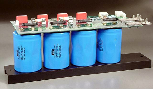
                The separate power supply board is where the 220uF 350v snap in caps go, but notice the caps are connected in series: the C45 negative terminal (dark box) is connected to the C46 positive terminal (open box)
                +(C45)- +(C46)- Ground

                parallel caps have a total capacitance equal to 1/220 +1/220 = 1/x so the total capacitance C45 +C46= x = 220uf but the trick is that the voltages are now additive, so you've turned 2 x 220uF/350v caps into one 220uF/700v cap!

                this is essential cause you can't buy a single cap which will work, the R71 and R72 resistors are sometimes called "equalizing resistors" and serve to make sure each series cap sees the same voltage, otherwise one could end up with 90% of the voltage and burn out way fast, they also allow the charged cap to discharge safely when you unplug the amp; a capacitor without a resistor across it can store a charge for a long time and discharge instantly when touched and kill you. Bigger value power supply caps are the dangerous ones; a 0.022uf cap holds very little charge!

                The way a tube amp power supply is (almost always) designed is to take a VERY high B+ voltage and feed it to the power amp tubes plate, a bit lower voltage to the power amp tube screens and then much lower voltages to the preamp tubes. All on a single rail from the power transformer (PT) through a series of series resistors which drop the voltages. B+ plates/screens/preamp tubes. The very low heater /bias and accessory voltages usually come off different PT taps and separate rails.

                You should feel comfortable with series and parallel resistors and caps. Voltage ratings on caps are minimum values, and cap values are MUCH more important in the signal path away from the power supply.

                Power supply cap 220uf vs 330uf little if any difference
                Signal path coupling capacitor 0.022uF vs 0.047uF big difference!
                Last edited by tedmich; 01-24-2012, 04:16 AM.

                Comment


                • #38
                  Originally posted by tedmich View Post
                  parallel caps have a total capacitance equal to 1/220 +1/220 = 1/x so the total capacitance C45 +C46= x = 220uf but the trick is that the voltages are now additive, so you've turned 2 x 220uF/350v caps into one 220uF/700v cap!
                  Ted, you lost me a bit here. 2 identical caps in parallel will give double the capacitance but not affect the voltage rating. 2 identical caps in series will give you half the capacitance but double the voltage rating.
                  From the schematic it looks like 4 caps in series-parallel so we end up with the equivalent of a 220uF 700 volt cap.
                  Originally posted by Enzo
                  I have a sign in my shop that says, "Never think up reasons not to check something."


                  Comment


                  • #39
                    Originally posted by g-one View Post
                    Ted, you lost me a bit here. 2 identical caps in parallel will give double the capacitance but not affect the voltage rating. 2 identical caps in series will give you half the capacitance but double the voltage rating.
                    From the schematic it looks like 4 caps in series-parallel so we end up with the equivalent of a 220uF 700 volt cap.

                    may have lost you but we both got to the same place, each set of (2) series caps comes in at 220uF/~700v, so we have 220 x 2 = 110uf/700v total. There are equations which let you calculate the "R balance" values using DIFFERENT caps to balance the voltages, and rail gun and laser guys regularly use N>4 series caps, like this big unit from apexjr.

                    550uf at ~1800v (2100v surge!) $35
                    Last edited by tedmich; 01-25-2012, 04:44 PM.

                    Comment


                    • #40
                      Originally posted by tedmich View Post
                      may have lost you but we both got to the same place, each set of (2) series caps comes in at 220uF/~700v, so we have 220 x 2 = 440uf/700v total.
                      Sorry to bicker and I don't want to derail the thread but we are not getting to the same place. We have four 220uf 350V caps. Each set of (2) series caps comes in at 110uf/700V, not 220uf. The final result of the 4 caps (110 in parallel with 110) is 220uf@700V, not 440uf.
                      Originally posted by tedmich View Post
                      parallel caps have a total capacitance equal to 1/220 +1/220 = 1/x so the total capacitance C45 +C46= x = 220uf but the trick is that the voltages are now additive, so you've turned 2 x 220uF/350v caps into one 220uF/700v cap!
                      This is the formula for series, you said parallel, I think that is a typo. However the equation works out to 110uf, not 220. You can not turn 2 x 220uf/350V caps into one 220uf cap. In parallel they add, in series they divide (opposite of speaker impedance formulas).
                      You want the OP to "feel comfortable with series and parallel resistors and caps" so I will hold you to that .
                      Originally posted by Enzo
                      I have a sign in my shop that says, "Never think up reasons not to check something."


                      Comment


                      • #41
                        Originally posted by g-one View Post
                        Sorry to bicker and I don't want to derail the thread but we are not getting to the same place. We have four 220uf 350V caps. Each set of (2) series caps comes in at 110uf/700V, not 220uf. The final result of the 4 caps (110 in parallel with 110) is 220uf@700V, not 440uf.
                        This is the formula for series, you said parallel, I think that is a typo. However the equation works out to 110uf, not 220. You can not turn 2 x 220uf/350V caps into one 220uf cap. In parallel they add, in series they divide (opposite of speaker impedance formulas).
                        You want the OP to "feel comfortable with series and parallel resistors and caps" so I will hold you to that .
                        According to the valve wizard you are correct.
                        Their example is 2- 100uf at 400 Volts in series= 50uf at 800Volts.
                        The Valve Wizard
                        at the bottom of the page.
                        Keep Rockin!
                        B_T
                        "If Hitler invaded Hell, I would make at least a favourable reference of the Devil in the House of Commons." Winston Churchill
                        Terry

                        Comment


                        • #42
                          Originally posted by g-one View Post
                          Sorry to bicker and I don't want to derail the thread but we are not getting to the same place. We have four 220uf 350V caps. Each set of (2) series caps comes in at 110uf/700V, not 220uf. The final result of the 4 caps (110 in parallel with 110) is 220uf@700V, not 440uf.
                          This is the formula for series, you said parallel, I think that is a typo. However the equation works out to 110uf, not 220. You can not turn 2 x 220uf/350V caps into one 220uf cap. In parallel they add, in series they divide (opposite of speaker impedance formulas).
                          You want the OP to "feel comfortable with series and parallel resistors and caps" so I will hold you to that .

                          silly me, you are right

                          gotta brush up the math skills!

                          Comment


                          • #43
                            Was never much for math myself, then the calculator changed everything .

                            I noticed the bias diode is missing from the schematic. But it is there on the circuit board so no problems. Also the caps polarity is shown wrong on the schematic, but the board is correct. Here is a revised schematic of the bias circuit:
                            Click image for larger version

Name:	markIIC+bias.jpg
Views:	1
Size:	43.6 KB
ID:	824060
                            Last edited by g1; 01-26-2012, 06:02 AM.
                            Originally posted by Enzo
                            I have a sign in my shop that says, "Never think up reasons not to check something."


                            Comment


                            • #44
                              Originally posted by tedmich View Post
                              silly me, you are right

                              gotta brush up the math skills!
                              C1 times C2, divided by C1 plus C2, equals two caps in series.

                              Comment


                              • #45
                                Originally posted by g-one View Post
                                Was never much for math myself, then the calculator changed everything .

                                I noticed the bias diode is missing from the schematic. But it is there on the circuit board so no problems. Also the caps polarity is shown wrong on the schematic, but the board is correct. Here is a revised schematic of the bias circuit:
                                [ATTACH=CONFIG]17019[/ATTACH]
                                what value of R83 R84 are used? Is there a variable bias mod? Figure a series 15k and 20k pot in place of R83 R84 would give you a decent voltage range (40-60v)

                                Comment

                                Working...
                                X