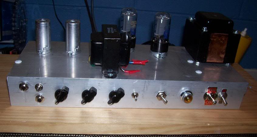
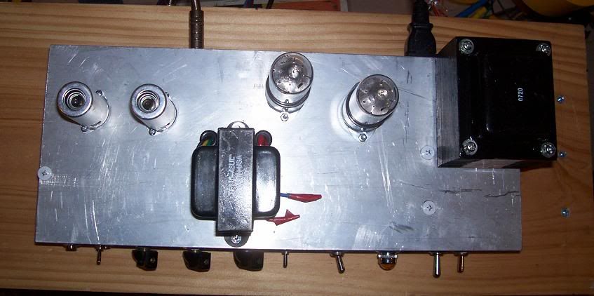
havent been in the 5e3 section for a while. my 5e3 build turned to a spare parts bin after not being used due to the hum, which was too much of a hassle to fix due to my bad choice of a chassis (had a small opening, and my wires were in 3d due to the placement of the board tubes and controls all being on different faces). this made things quite difficult to do any work on it once there were many connections in there.
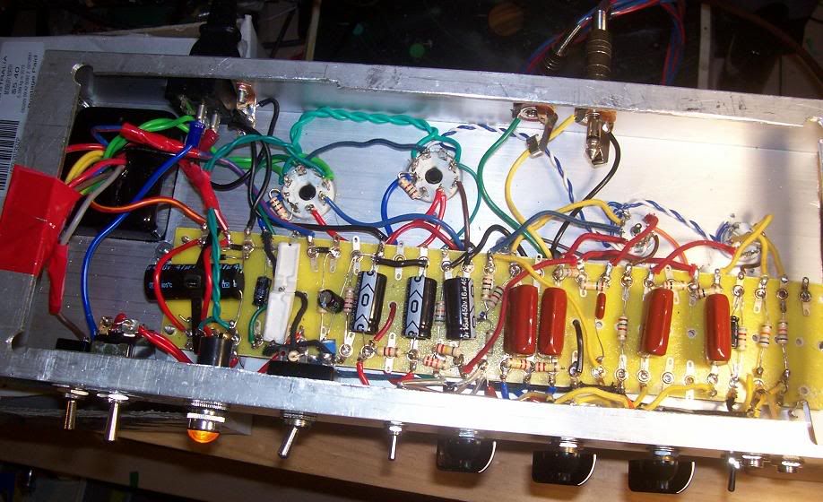
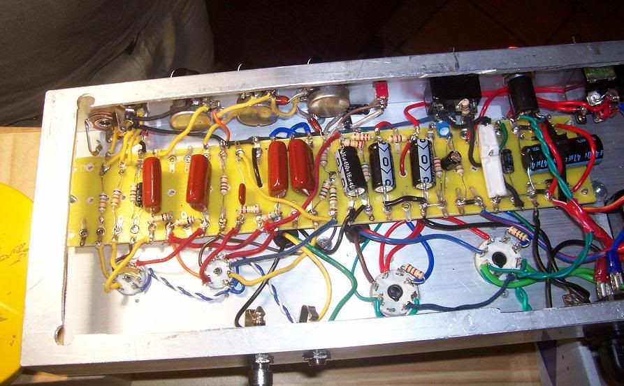
so the other day i decided to rip out the board and all its connections, the sockets and pots and put it into a chassis made from a 150x50mm aluminium extrusion. things fit much nicer. i wired the power supply as a 300vac winding to a bridge rectifier, and then put it into a 47ohm resistor to get closer to the right voltage. there was also a 47uf cap before the 47 ohm resistor. after this it goes into the normal power supply with 16uf caps and 4k7/22k resistors. this was to get rid of much of the power supply ripple, and get some sag through the resistor. i also added a -ve voltage supply so i could put a switch in to switch it to fixed bias. i also added a voltage divider from the last preamp supply to float the heaters at ~40-60v. i only put 2 inputs (1 per channel) and put a switch to link the 2 channels at the input. theres also a switch to change the cathode bypass cap on the gain stage before the PI.
having done a few things there that should have eliminated alot of hum i was surprised how much hum there actually was. i did a bit of reading and it seems i need to separate the filter cap ground for the preamp from the others, and i suspected having the power supply ground connected to the leg of the PT bolt could possibly effect hum. this should minimise hum for the amp.
the main issue i have with the hum is for the bright channel. the hum is so bad that it is very unusable. i wouldnt be surprised if on full the hum started to distort. the hum comes from before the vol pot, and is alot worse than the other channel. i disconnected the lead going from the coupling cap to the vol control, and there was no hum coming from the channel. the gain stage has the stock shared 820ohm/25uf cathode bias, so its not an issue with that, otherwise it would effect both channels. the plate resistor comes from the same supply as the fender layout, so i dont see how the hum could be coming from there (im sure some does, but not the bulk of it).
i've just got a scope, and am a still learning how to use it effectively. i am seeing some hum on the output from the coupling cap (where the lead to the vol pot would be). there is no noticeable hum on the output of the normal channel (i did turn the vol to full so that there was a full 1m resistance to ground across the pot).
i've done a bit of chopsticking to the wires going into the tube socket, and there doesnt seem to be an audiable difference.
does anyone have any ideas as to what the reason for so much hum on the bright channel? i will get some photos when i get home later.
edit: i am using a split grounding circuit of some sort. i have the filter caps and the cathodes of the 6v6's connected to a copper plate that is bolted to the chassis (was connected to the PT connection bolt, but i may move that). the other connections are daisy chained together and connected to one of the input jacks. i hear that daisy chaining isnt the best way, but i've done it before without issues. the main issue i have is the inst channel issue. i want to get that right before doing the minor fixes.


Comment