Announcement

Collapse
No announcement yet.

Hoffman Style Grounding Question?

Collapse
X
 
  • Filter
  • Time
  • Show
Clear All
new posts

  • Hoffman Style Grounding Question?

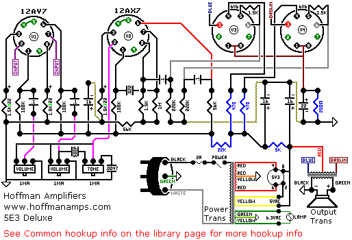
    Hey guys so im working out the research for a 5E3 build and I like the layout for the Hoffman 5E3. I just have a question about the ground buss idea he uses and what to do using isolated input and output jacks. Should I be soldering that buss wire to the back of all the puts then connecting the Isolated input grounds to that and thats it or do I need to run another wire from that buss to a ground lug near the inputs? Also for the outputs do I need to run the ground for that back to the ground point close to the power transformer or can I ground to a lug close the the outputs?

    Thanks for the help

    Neill

  • #2
    Don't bother isolating the input & output jacks. Use regular metal switchcraft jack sockets they ground directly to the chassis, ground the buss wire (solder to all pot backs, as will be grounded pot terminals and the 0.0047uf tone cap) to Normal 1 input jack. Run the preamp ground from the board to this jack too.

    OT common is grounded to the main speaker jack ground lug (also tied to the main speaker jack 'switch' terminal).

    Comment


    • #3
      And if I already have the isolated jacks should I get some grounding washers or can I just put a grounding lug at that point in the chassis and run the buss down to that?

      Comment


      • #4
        Yes, you can put a grounding lug at that end of the chassis. You could try grounding the speaker at a solder tag on the nearest power tube socket nut to the speaker jack.

        Notice on the Hoffman scheme that the 220K power tube grid return resistors, screen supply & main filter caps, power tube cathode resistor & cap ground to a PT bolt. The preamp filter cap is grounded to the preamp ground lug.

        Comment


        • #5
          Doug uses two grounds: dirty, between the PT and C1, where you should connect all grounds for the power stage - from the 220K grid return to the output jacks; clean, close to the input jacks, for all low level nodes. Both should use 6-40 or larger bolts with lugs - don't use PT bolts for this. Plus of course a dedicated earth close to the mains inlet.


          There's no need for isolated jacks.

          Comment


          • #6
            It's fine to use a PT bolt (upper right) for the power amp (dirty) grounds. Use another PT bolt for the AC Cord (upper left).

            Comment


            • #7
              Everyone seems to have their favorite way to ground. I have built several of the old Fender Tweed amps (5F2a, 5E3, 5B3 etc.) and here is what I do..I do buss grounding as a modified Hoffman grounding scheme. That is I run a buss bar (wire) from one end of the board to the other. I ground everything to this buss (except the Mains ground which is on a ground terminal by it's self) and then ground the buss right at the input jacks on a terminal mounted there. I don't even try to solder to the back of the pots. Keep ever thing in the correct order as you go down the buss. I get no hum. This works for me. I do not use the power transformer bolts for a grounding point and personally think that that is not the correct thing to do. I think that grounds should be on a terminal that is bolted to the chassis using a star washer and then loctited. The mains ground the same way and make the mains ground wire longer than the hot and neutral wires such that if they pull loose the ground wire will be the last to go. Just my way of doing things.

              Comment


              • #8
                Ok so it seems there are a number of ideas for grounding. Is there anyone out there that has experience using the different styles of grounding and can they say which one gives the best results. This can include using the normal layout too if it turns out the hoffman design isn't worth the hype.

                For reference I intend to use switchcraft style jacks without isolation (because I already have these) and an aluminum hammond 13.5x5x2 chassis for a combo build.

                Comment


                • #9
                  Not really, because once we have settled into a method that works, we all keep repeating that method (if you try a different scheme with every amp, you can end up with going round in circles)...I build very quiet amps, I'm sure the others do too. The proof of the pudding is in the execution, you might end up taking aspects of all the suggestions.

                  The Hoffman layout is superior to the stock 5E3, use it, keep the grid wires from the coupling caps to the power tubes as short as possible, shield input wires.

                  Comment


                  • #10
                    Yeah I think Ill just stick to the basic Hoffamn suggestions. Just to be sure of that my method should be.

                    Hoffman board with power section grounded to a lug near the transformer, Input grounds tied to the ground of the normal input which also has the ground bus from the back of the pots, Output jacks are grounded themselves so just have the common of the OT secondary to that. HT centertap should join at the ground of the first filter cap? and ill be using a virtual center tap on the heaters should I solder that to the + side of my power cathode to elevate that?

                    Then Bing Bang Boom I should have a pretty quiet amp.

                    Comment


                    • #11
                      I do not use the power transformer bolts for a grounding point and personally think that that is not the correct thing to do. I think that grounds should be on a terminal that is bolted to the chassis using a star washer and then loctited. The mains ground the same way and make the mains ground wire longer than the hot and neutral wires such that if they pull loose the ground wire will be the last to go. Just my way of doing things.
                      +1. Best practice and safest way.

                      Comment


                      • #12
                        HT centertap should join at the ground of the first filter cap?
                        Yes. Check Grounds for more info.

                        ill be using a virtual center tap on the heaters should I solder that to the + side of my power cathode to elevate that?
                        Yep. You'll get around 20V, quite useful when it comes to reduce heater noise *and* protect the 12AX7 used in the cathodyne PI.

                        Oh, and don't forget the safety earth.

                        Comment


                        • #13
                          "and ill be using a virtual center tap on the heaters should I solder that to the + side of my power cathode to elevate that?" Sure, you can if you want, I wouldn't say that it is necessary (you can also ground the 100ohm resistors to the lamp assy, or to a ground point nearby), but give it a go, it is a method used with some success.

                          Comment

                          Working...
                          X