Ad Widget

Collapse

Announcement

Collapse
No announcement yet.

Question about filaments on 5e3 triode electronics wiring diagram

Collapse
X
 
  • Filter
  • Time
  • Show
Clear All
new posts

  • Question about filaments on 5e3 triode electronics wiring diagram

    I'm still a bit new at this, so questions keep arising as I try to get my first amp built so here it goes...

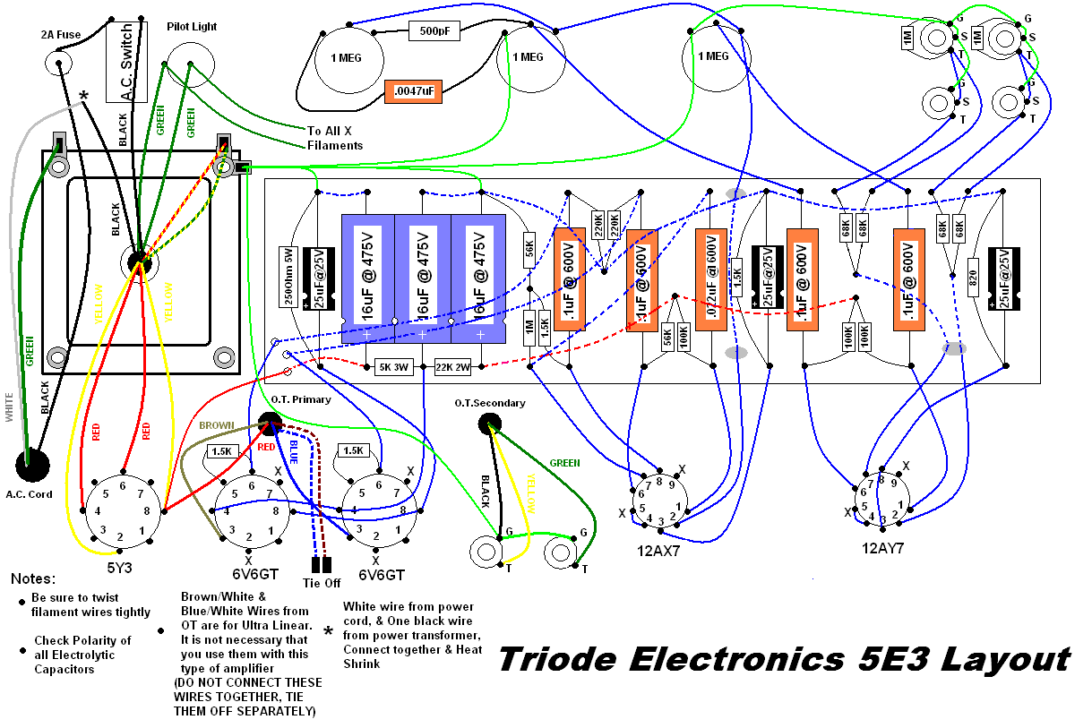
    The following pictures says that the wires coming from the pilot light need to go to "all x filaments." I see that the tubes have x filaments labeled on the 7 and 9 pins, but how should I connect them; just run a continuous wire through each of those joints then ground off? I'm really not sure about this so if any body could shed some more light it would be greatly appreciated.
    Last edited by volker_77; 01-15-2009, 07:25 AM. Reason: grammar

  • #2
    Originally posted by volker_77 View Post
    I'm still a bit new at this, so questions keep arising as I try to get my first amp built so here it goes...

    The following pictures says that the wires coming from the pilot light need to go to "all x filaments." I see that the tubes have x filaments labeled on the 7 and 9 pins, but how should I connect them; just run a continuous wire through each of those joints then ground off? I'm really not sure about this so if any body could shed some more light it would be greatly appreciated.
    Hi volker_77,

    the wiring has simply to be a "parallel" one, meaning that one "X" wire coming from the pilot lamp has to go to pin 2 ( not 9 ) of both output tubes ( the bigger ones ), then to pin 9 of all the preamp tubes ( the smaller ones ).

    The other "X" wire from the pilot lamp has to go to pin 7 of both output tubes ( the bigger ones ), then to pin 4 and 5 ( jumpered together, see layout ) of all the preamp tubes ( the smaller ones ).

    I think you just missed to see the second "X" on each socket....

    BTW, the most common output tubes ( 6L6, 6V6, 5881, EL34, etc. ) have their heaters connected to pins 2 and 7, while the most common preamp tubes ( 12AX7, 12AU7, 12AT7, ECC81,ECC82,ECC83 etc. ) have the heaters connected to pins 4-5 ( to be externally jumpered for 6,3 V "parallel" operation, like in your case ) and pin 9.

    None of the two "X" wires has/needs to be grounded, the wiring will simply "end" at the rightmost tube.

    To minimize hum coming from the heaters, you should evenly twist the two "X" wires as you run them from the pilot lamp all the way through all the sockets.

    It's also good practice to add a "hum balance pot" to help to further reduce any residual hum : to do this you need a 220 Ohm potentiometer ( a "normal" 0,5 W is OK, a 2W potentiometer even better ); simply connect the two potentiometer external lugs to the "X" wires coming from the pilot lamp ( paralleling it with twisted wires just like you did for the heaters ) and then connect the potentiometer's center lug to ground. Start with the potentiometer centered, then try to slowly rotate the potentiometer with the amp on; you should be able to find a "sweet spot" where the amp hums audibly less.

    Oh, I'd like to add a word of caution, as you state you're pretty new to this....as you might have already read, the voltages inside your amp can ( and possibly will, if you're not extremely cautious ) kill you, so make yourself familiar with safety procedures ( draining capacitors etc. ) before going any further.

    Hope this helps

    Best regards

    Bob
    Last edited by Robert M. Martinelli; 01-15-2009, 09:35 AM.
    Hoc unum scio: me nihil scire.

    Comment


    • #3
      Let me add to what Bob said.

      This drawing is poorly done. It is confusing. TO someone already familiar with wiring amps, it is easy to follow, but for someone inexperienced like yourself, the drawing implies something completely wrong.

      It LOOKS like they would have you wire both green wires to all the X points all together. This will result in a dead short across the power.

      It is AC, so there is no polarity to worry about.

      They SHOULD have labelled the green wires X and Y. Or X and something other than X for the other. Likewise at each tube socket, one pin shuold be X and the remaining pin Y. Thus one of the green wires should go to ONE heater pin on each socket. Then the other green wire goes to the remaining pin on each socket.

      I am not sure why you would think the green wires also needed to be grounded. Unless it is because OTHER green wires are grounds here.

      Bob's suggested hum balance pot is a good idea. The drawing shows no connection to ground for the heaters. That is odd to me. Even just grounding one side of the heaters will reduce the hum. The balance is even better.
      Education is what you're left with after you have forgotten what you have learned.

      Comment


      • #4
        There is a heater centre tap (grn/yel) shown, grounded at the PT bolt.

        Leave this disconnected (tie off & insulate) if you want to use a hum balance pot.

        Comment


        • #5
          Hi MWJB,
          I didn't think of the green-yellow wire out of the PT as the heaters winding's center tap, I thought it to be a ground connection ( here in Europe green-yellow is the color code for Earthing ). If that actually is the winding center tap then +1 on what you say, it has to be obviously lifted and insulated when using a hum balance pot.
          Best regards
          Bob
          Hoc unum scio: me nihil scire.

          Comment


          • #6
            All other grounds shown are solid green (which is a little confusing to me as it makes me immediately think of the heater supply).

            I live in Europe too, I did buy a spool of grn/yel wire for grounding...but it looks just awful! :-)
            I normally use black for cathodes & grounds, which is fine as my wall AC wires are blue & brown - as opposed to black & white in the US, which could cause confusion there (sigh).

            I guess if there is a moral for a newbie, never assume a wire does a particular job just because of its colour, always check what the wire actually connects to/transformer legends. Once you've got a scheme that works for you, stick to it.

            Comment


            • #7
              MWJB is right, that would be the center tap for heaters. In that case, it is sufficient. Don;t add anything. A grounded center tap AND a hum balance pot is just begging for a burnt out blance pot.
              Education is what you're left with after you have forgotten what you have learned.

              Comment


              • #8
                Thaks for all your guys help. Just one question left. I see on the 12 AX7 and 12 AY7 tubes that the x filiments are supposed to be connected to the 4 spots. My question is do I run the green wires from 5 to 5. Or do I run it from the 4 spot on the 12 ax7 to the 5 spot of the 12Ay7? Hopefully this isn't worded too confusingly. If it is let me know and I'll try to be more specific.

                Comment


                • #9
                  connect one leg of the heaters to 12AX & 12AY pins 4 & 5 linked, connect the other leg of the heaters to pin 9.

                  Do a search on some completed build pics (not original 5E3 as these are wired differently to your layout).

                  Comment

                  Working...
                  X