Ad Widget

Collapse

Announcement

Collapse
No announcement yet.

Need help with 5f2a mod

Collapse
X
 
  • Filter
  • Time
  • Show
Clear All
new posts

  • Need help with 5f2a mod

    First time poster, been lurking awhile however.

    this is gonna be my first build, and I've chosen a 5f2a.


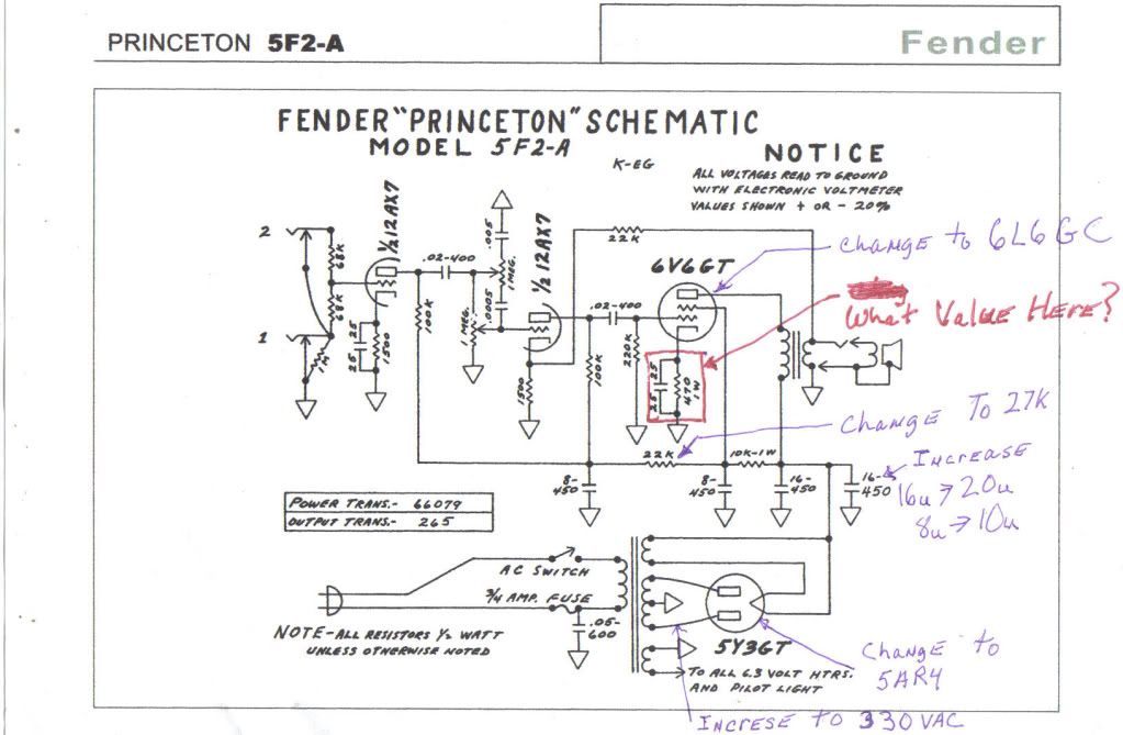
    but I want a little more power and more clean headroom, so I'm gonna mod the circuit to use a 6L6gc. What I need help with is determining the correct values for the cathode bias resistor and associated bypass cap.
    thanks in advance
    Frank

    <a href="http://s625.photobucket.com/albums/tt334/big-daddy-59/?action=view&current=Modified5f2a.jpg" target="_blank"><img src="http://i625.photobucket.com/albums/tt334/big-daddy-59/Modified5f2a.jpg" border="0" alt="5f2a schematic modified for 6L6"></a>
  • #2
    fixed the link to graphic

    Comment


    • #3
      Hi Frank

      For a SE 6L6GC 5F2A, the changes you have suggested would probably be okay, But you could use a PT that has a HT (High-Voltage) winding of about 325-0-325VAC at say 70mA minimum (altho' I would tend to make it 90mA or 120mA), and a heater winding of 6.3V @ 2A and, if you are using the rectifier tube (which I think adds flexibility) a winding of 5V @ 3A so you cab run a variety of rectifiers from 5Y3GT to 5U4G to 5AR4. This way you will be able to run either a 6V6 or a 6L6GC.

      You will also need an SE OT that is about 15W, preferably with a choice of secondary taps so that you can get either 8K, 6k6 or 4k or 3k2 primary load resistance by switching the speaker to a different tap.

      The cathode resistor will also need to be switchable between 470R for a 6V6 and 250-270R for a 6L6GC.
      Building a better world (one tube amp at a time)

      "I have never had to invoke a formula to fight oscillation in a guitar amp."- Enzo

      Comment


      • #4
        Thanks Tubeswell
        the spec for the power tranny are as follows

        Comment


        • #5
          Fitting a 6L6 with that PT is not going to significantly increase power over a 6V6, the 6L6 will draw more current, pulling down B+, but you might still like the tone of it.

          40-50uf will be fine as the first filter cap.

          Use a 10W rated cathode resistor on the power tube, 470ohms will be fin up to around 410vdc plate voltage. Use a 100v rated bypass cap @ 100uf rather than 25uf, will help punch.


          Personally, to get a reasonable increase in performance from the 6L6 I'd be looking to go fixed bias and maybe 350-0-350VAC PT.

          Comment


          • #6
            I don't know, just a noob, but by my bass ackwards engineering of the power supply I ought to have about 420-440 VDC at the plates.

            thats using 330-0-330 taps on power transformer, and a 5AR4 for the rectifier

            and according to Tubeswell I should be good on filament current for both 6.3v and 5v taps

            Comment


            • #7
              A 6L6 draws 900mA off the heater winding, and a 12A_7 heater draws 300mA. Together with the lamp (300-500mA), if you have at least 2A there you will be alright.

              A 5AR4 draws just under 2A off the 5V winding.

              660-660 with a SS Full Wave Bridge rectifier should give you a B+ around 460VDC.

              In cathode bias and class A, a 6L6GC with a plate voltage of about 460 draws about 50mA off the HT winding and a 12AX7 draws about 4mA tops.
              Last edited by tubeswell; 06-18-2009, 08:48 PM.
              Building a better world (one tube amp at a time)

              "I have never had to invoke a formula to fight oscillation in a guitar amp."- Enzo

              Comment


              • #8
                "I don't know, just a noob, but by my bass ackwards engineering of the power supply I ought to have about 420-440 VDC at the plates, thats using 330-0-330 taps on power transformer, and a 5AR4 for the rectifier" If you do end up with those voltages, your amp might only take certain brands of 6L6, as it'll draw 70mA plus with a stock 470ohm cathode resistor and not all brands will take it (I had an Epi Tube 10 that ate SEDs). But I wouldn't asssume that right now because, firstly the current draw of the tube will affect final B+, plus your cathode voltage will need to be deducted from "plate to ground voltage". Cathode biased amps tend to show less plate voltage than fixed bias amps for these 2 reasons.

                "660-660 with a SS Full Wave Bridge rectifier should give you a B+ around 460VDC." No, 660-660VAC with a full wave BRIDGE would give 924vdc...+/-.

                330-0-330VAC, centre tapped, with a full wave SS rectifier should give 460v odd, but that would be in fixed bias with a modrate current draw. To put it in perspective, to get 465v at the plates with a SS rectifier I usually need a 345-0-345VAC PT and I usually use PTs with twice the expected capacity.

                "In cathode bias and class A, a 6L6GC with a plate voltage of about 460 draws about 50mA off the HT winding" For the life of me I cannot imagine how you came up with the 50mA figure? With a 660-680ohm cathode resistor it might (accepting that actual plate voltage will be around 425vdc after subtracting cathode voltage) but the tube won't really be biased to class typical A type currents, if we are assuming that we are aiming for an idle current halfway between cut-off & saturation?

                With the PT suggested, a GZ34 and a 470ohm cathode resistor, you might see a little over 410vdc?

                Comment


                • #9
                  Originally posted by MWJB View Post
                  "660-660 with a SS Full Wave Bridge rectifier should give you a B+ around 460VDC." No, 660-660VAC with a full wave BRIDGE would give 924vdc...+/-.
                  I didn't say 660-0-660. I mean't a HT winding that measures 660 from one side to the other without a centre tap

                  Originally posted by MWJB View Post
                  330-0-330VAC, centre tapped, with a full wave SS rectifier should give 460v odd, but that would be in fixed bias with a modrate current draw. To put it in perspective, to get 465v at the plates with a SS rectifier I usually need a 345-0-345VAC PT and I usually use PTs with twice the expected capacity.
                  OK I have gotten 430 with 330-0-330 using 6L6CG cathode biased in a PP amp with a GZ34, so I was figuring with one tube and SS rect, it would be higher (Admittedly the PT was rated for 180mA).

                  Originally posted by MWJB View Post
                  "In cathode bias and class A, a 6L6GC with a plate voltage of about 460 draws about 50mA off the HT winding" For the life of me I cannot imagine how you came up with the 50mA figure?
                  I was using the AX84 calculator as a guide.
                  Building a better world (one tube amp at a time)

                  "I have never had to invoke a formula to fight oscillation in a guitar amp."- Enzo

                  Comment


                  • #10
                    Originally Posted by MWJB
                    "660-660 with a SS Full Wave Bridge rectifier should give you a B+ around 460VDC." No, 660-660VAC with a full wave BRIDGE would give 924vdc...+/-.

                    ...then Tubeswell said, "I didn't say 660-0-660"

                    ...no, you said 660-660, really should be expressed as 0-660. This determines that there is no centre tap, otherwise you would say 660-0-660 ("0" being the centre tap). A bridge rectifier does not use the PT centre tap and gives roughly 1.41 times the whole of the AC B+ winding, so 660*1.4

                    Your earlier recommendation of a 250-270ohm cathode resistor, with the PT/rectifier in question would give far more than 50mA idle current, and certainly much less B+ voltage than 460vdc. I'd go with 470 on the first instance, perhaps keep plate current around the 60mA mark.

                    However, I still think that fixed bias is the way to go to get more efficient use out of the 6L6, compared to 6V6. Otherwise, gains in performance may be negligible due to the see-saw effect of the 6L6 drawing more current & subsequently, less B+ voltage. Differences in tone might be just what you want, but increase in power may be nominal.

                    Comment


                    • #11
                      Ahhh - I assumed that with a HT of 660VAC from one end of the winding to the other, that you'd be looking at 330 either side of the 'neutral' part of the voltage swing, and hence you'd use 330x 1.4142 to get ~460VDC - My bad (Ah well - can't win 'em all )
                      Building a better world (one tube amp at a time)

                      "I have never had to invoke a formula to fight oscillation in a guitar amp."- Enzo

                      Comment


                      • #12
                        Well, using a "full wave diode rectifier" (but not a bridge) with a centre tapped PT, you would. But the fly in the ointment was the term "bridge" rectifier.

                        Comment


                        • #13
                          ok guys I do have a couple of alternate cathode resistors coming with the rest of my parts. one of you said the schematic specified 470R might result in bias currents being a bit too high. How do I do the math to guesstimate the proper value that would result in safe operation or at least a conservative starting point where I won't blow stuff up.

                          Comment


                          • #14
                            If you are going to use a 6L6/5881 and don't want to worry about dissipation, then chuck in a 660-680ohm resistor and forget about it. 470ohm will be fine so long as your plate voltage is not much over 410vdc (with that resistor).

                            There are too many variables to accuratey calculate with math.

                            Comment


                            • #15
                              Well I put it together today,staing going thru the step by step start up, everythings going well. Put the tubes in, start measuring voltages,and....POP!! the 25u25v cathode bypass cap on the power tube explodes. I think it was just too much voltage going thru it. Gonna order a new cap,higher voltage this time and see how she works .

                              Comment

                              Working...
                              X