 Tweet
Tweet
Originally posted by Sea Chief
View Post
-
Yep, the only caveat is finding somewhere to mount the components. -
-
The contemporary crop of tubes branded as 5Y3 have lower voltage drop than the traditional ones from the 60's. If you can find a NOS 5Y3, it will lower the B+ some.
What do you have for a 12AX7? Have you tried any other tubes?WARNING! Musical Instrument amplifiers contain lethal voltages and can retain them even when unplugged. Refer service to qualified personnel.
REMEMBER: Everybody knows that smokin' ain't allowed in school !Comment
-
Not yet. At the mo its a generic sovtek 12ax7, as is the 5y3. The sound is quite hard and unforgiving and not too inspiring but how much of that is due to these tubes I cant begin to tell, or have enough experience yet of tubes to know. How much is a NOS 5Y3, and a better 12AX7?Originally posted by loudthud View Post
Its great I can start thinking on these lines now- what a relief.Comment
-
Lots of suggestions coming.. its all a bit overwhelming tbh I dont know my oorse from me elbow. How do you higher the preamp voltage then? sounds like upping the gain here makes sense if I can. I like the idea of the 'added sag resistor and power tube grid resisitor' to take off a bit of harsh too, although Ive absolutely no idea what it means but it sounds good!Originally posted by Chuck H View PostComment
-
Easiest to try a vintage 5Y3 rectifier first, might make a dramatic difference -
Just find a tested used one for a few bucks, it's a common tube... if you like the sounds then stock up!Comment
-
GROWL is good! I prefer less NFB - up to none at all - on the champ amps I've played around with.
[SNARK]With the screen on the same node as the preamp, and the grid-leak bias, I'm supposing this wasn't one of the most popular models...[/SNARK]Originally posted by Jazz P Bass View Post
But I recognize the Pi filter here (before the B+ node) as a way to get ripple out of the power tube, true that. Good call.If it still won't get loud enough, it's probably broken. - Steve Conner
If the thing works, stop fixing it. - Enzo
We need more chaos in music, in art... I'm here to make it. - Justin Thomas
MANY things in human experience can be easily differentiated, yet *impossible* to express as a measurement. - Juan Fahey
Comment
-
Sea Chief,Originally posted by Dave H View Post
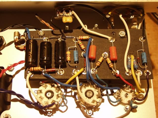
A simpler way to reduce the B+ voltage would be to replace the wire between pin 8 of the 5Y3 and first filter cap on the board with a 470 ohm 7W resistor (Maplin). It would only take a few minutes to do and it should fit in just fine. Just make sure the wire to the OT is connected to the first filter cap and not pin 8 of the 5Y3. On your picture it looks like it could be connected to pin 8 via a link to pin 7.Last edited by Dave H; 10-14-2014, 01:53 AM.Comment
-
Since Sea Chief isn't a tech I'm thinking it might be easiest for him if we just used his photos and painted red arrows on them with instructions. Or something like that. No one wants to be the bomb squad guy wondering which wire to cut "Take two placebos, works twice as well." Enzo
"Now get off my lawn with your silicooties and boom-chucka speakers and computers masquerading as amplifiers" Justin Thomas
"If you're not interested in opinions and the experience of others, why even start a thread?
You can't just expect consent." HelmholtzComment
-
Jazz. Regards NFB and related from an earlier post. Note the feedback resistor in the 600 is 2.2k, not 22k as in the 5E1 and 5F1.
I think when comparing the Champion 600 and the older Champs, you need to include both 5E1 and 5F1. 5E1 has the choke on all B+. the 5F1 got rid of the choke. Notice the 5F1 removed the cathode bypass on the input stage, probably to back off the gain some. Maybe the amp was breaking up too easily.
Now on the 600 Champion, the input stage bypass has returned and they even bypassed the second stage, so the amp now has lots of gain, tastes have changed. But on the old models, NFB went into the cathode of the middle triode. But a bypass cap will bypass NFB as easily as it bypasses any other audio. SO they bypassed only the cathode resistor, and added a 47 ohm to ground to provide NFB injection but still allowing stage bypass. The old NFB was 22k/1.5k. but to get that same level would have required another 1.5k under the existing one. So to make levels equivalent they lowered the feedback resistor to 2.2k and the tail resistor to 47 ohms.Education is what you're left with after you have forgotten what you have learned.Comment
-
That sounds good Dave H. I have a 470r 10w.. any good? I guess will act as a bigger 'heat sink' if thats the idea, but will its bigger size remove more V? My noggin say no.Originally posted by Dave H View Post
I can remove the white wire from rec pin 8, leaving it from the the 1st filter cap, and switch it over to pin 7 of the rec (IE used as a junction only, to connect the OT as it is already here/ remove the link to pin 8 of course). Then put the R fatso in between 1st filter cap/ with the white wire as it is, and rec pin 8.
Is that sort of the right way of thinking to do such an addition?
[cobbled together? the very cheek!)
Comment
-
Well, now I must apologize for that statement.Originally posted by Sea Chief View Post
It is rather a nice build.Comment
-
Sea Chief,
With the feedback resistor gone you can now bypass the second preamp cathode for a lot more gain. Use a 2.2uf to 22uf electrolytic capacitor with a voltage rating 10V or higher. Add it parallel to the circled resistor with the negative end toward ground.Attached Files"Take two placebos, works twice as well." Enzo
"Now get off my lawn with your silicooties and boom-chucka speakers and computers masquerading as amplifiers" Justin Thomas
"If you're not interested in opinions and the experience of others, why even start a thread?
You can't just expect consent." HelmholtzComment
-
-
-
Ah ok I could do this in a jiffy. Neg twds top of pic then.Originally posted by Chuck H View Post
Can you tell me if my 10w 470r resistor is any good? (and my method of fitting #206 is not madness)?Comment

Comment