Ad Widget

Collapse

Announcement

Collapse
No announcement yet.

5f2a filter cap variations

Collapse
X
 
  • Filter
  • Time
  • Show
Clear All
new posts

  • #16
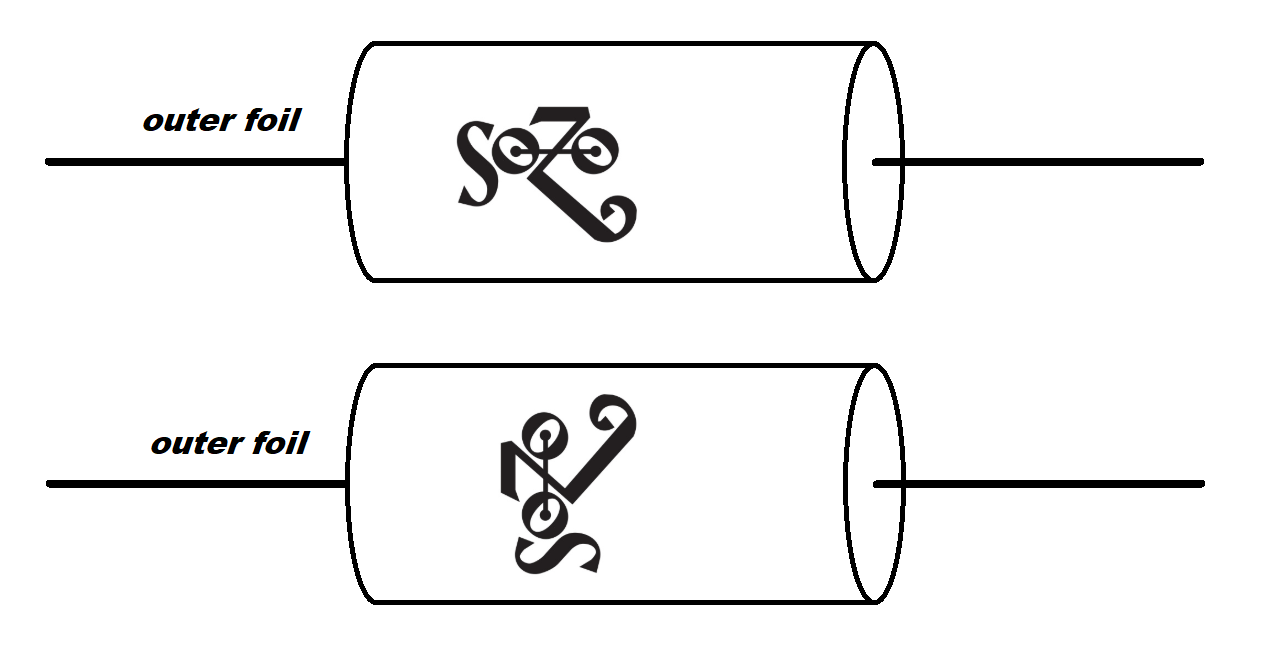
    Well I looked at a bunch of pictures and it seems that the outer foil IS marked. Or it was.?. At any rate, it's the lead at the top of the logo or the beginning of the logo depending on the logo orientation. This is the same aspect other suspiciously similar looking caps of another brand have for the outer foil as well.

    I won't go into how little regard I have for boutique caps and foil orientation... Oh, wait.?. I guess I just did But seriously, whatever makes you believe in your project and it's relative quality and goodness will improve personal confidence and therefor tone. Because you have to believe in it to love it. That's a very real thing so it's all good.
    Attached Files
    "Take two placebos, works twice as well." Enzo

    "Now get off my lawn with your silicooties and boom-chucka speakers and computers masquerading as amplifiers" Justin Thomas

    "If you're not interested in opinions and the experience of others, why even start a thread?
    You can't just expect consent." Helmholtz

    Comment


    • #17
      Thanks for all the expert info guys. Much appreciated. So here's a rough layout diagram of what I'm going for, with a few questions:

      I hope I've understood things correctly - the input jack 0.01uF caps to ground are in addition to the grounds to the main star point and should be as short cabling as possible? So ideally soldered to the chassis right next the jacks instead of run to the main star ground near by?

      I've ended up moving the speaker jack to a position between the 5Y3 and 6V6 as it was getting a bit congested in it's original spot with the added switches. I'm hoping it may be beneficial moving it further away from the preamp tube anyway. Thoughts?

      I'm going for shielded cable from the input jacks and volume pot - does it make a difference if the 68k grid stopper resistors are positioned at the jack end or the tube end? I've seen people do it both ways.

      Thanks.Click image for larger version

Name:	New 5f2a layout -Star Ground - isolated jacks v.1.png
Views:	1
Size:	654.6 KB
ID:	856877

      Comment


      • #18
        The impedance and NFB switch have the same influence (relative to proximity) as the output jack. That's because it's the same signal on those circuits (it makes sense if you consider that). So, ordinarily you would get some possible benefit from locating the output jack further from the input and preamp circuitry, but not in this case.

        I have to say I don't understand the implementation of the .01 caps across the input jack grounds. Did we cover this somewhere and I missed it? Since you have a ground point near the input such that you won't have any significant lead length for your grounds I would qualify those caps as shorted and therefor doing nothing. Do you have a link to the reference for why you are including them?

        Also, you're sort of missing the point of the star ground scheme by running your input jack grounds to the cathodes and then from that point to ground. You also have your volume control ground going to the filter cap and then to the ground point. But the biggest oops is that you have the output jack ground to the preamp filter node (with the volume ground lead) and then to the star ground point. The spirit of star grounding is that all grounds radiate from one point (like a star?). If it's a matter of convenience and not overcrowding a small ground point then there are alternative layouts that already ignore a star grounding scheme that should work better than what you have.
        "Take two placebos, works twice as well." Enzo

        "Now get off my lawn with your silicooties and boom-chucka speakers and computers masquerading as amplifiers" Justin Thomas

        "If you're not interested in opinions and the experience of others, why even start a thread?
        You can't just expect consent." Helmholtz

        Comment


        • #19
          Thanks Chuck,

          I was intending the 0.01uF caps as RF caps, going by the recommendations in the below links - however I found the explanations unclear as they recommend the main ground be at the input jack end of the chassis and also to include these caps on separate short leads. Would these 0.01uF caps just apply to situations where the main ground point is further away from the input jack?

          https://www.aikenamps.com/index.php/grounding

          https://ampgarage.com/forum/viewtopic.php?t=28892

          With the grounding I was going for local ground nodes at each amp stage which then connect to the main ground connection near the input jacks. As advised here: https://www.aikenamps.com/index.php/grounding

          Maybe I have misinterpreted the input jack ground connection below:

          “A good analogy is to think of an amplifier power supply distribution as a river. All the small currents from the preamp stage feed into a larger river, which has the heavier currents from the output stage, and the still heavier currents from the power supply. You want each successive stage farther "upstream" from the power supply, so the heavy currents don't influence the smaller ones. In the case of the input jack ground, it is the farthest point upstream from the power supply, so it should be connected directly to the ground point of the first cathode resistor. If you give it an alternate path to ground through the chassis, it can be influenced by ground currents in the chassis. Think of the first stage as amplifying the difference between the signal on the grid and the signal at the ground side of that stage's cathode resistor. If you have a long path back through the chassis to get from the input jack ground to the cathode resistor ground, it can pick up all sorts of stuff along the way. Keep it short, and use quality shielded cable, with the input jack isolated from the chassis, and the shield grounded at the ground side of the cathode resistor for the first stage. “

          As far as the output jack ground is concerned I had read that if using a negative feedback circuit it must be run back to the stage that the NFB returns to.

          Comment


          • #20
            Ah... Ok. Well far be it for me to take a different position from Randall! But I will say that I don't see the advantage of the RF caps when your input grounds can be kept short and the star ground is only an inch from where you would ground the caps anyway. Also, the 68k input resistors has a significant low pass filter affect that will typically be enough to block RF. With the combination of the near input star point, the short input ground lead and the 68k input resistors I just think the RF filter caps are redundant. You could always add them later if your local radio station is coming though your amp.

            As to the grouping of local circuitry before going to the star... Absolutely. But without some consideration there are still ways to have the wrong circuits sharing a ground lead. Sort of exclusive to your project would be the need to ground the isolated output jack with the preamp filter node. Because your amp will only have one preamp tube! Usually it's a later stage where the NFB is applied so the output jack would not be grounded with the preamp filter. But let's try and do the best with what we have considering that some ideologies for grounding and design are at some odds here.

            EDIT: On further consideration I think that in this case the least bad choice would be to ground the output jack with it's own filter. Having the highest current signal ground share a node and lead with the filter circuit that decouples the first gain stage. I'll gladly accept corrections if I'm wrong.

            If you localize the tone and volume control grounds at the pots and then head to the star point you won't have your preamp sharing a ground lead with the output jack. Since it's usually best to go directly to ground for the input jack grounds. So rather than localize by separating the input jack grounds and taking them to a board node for the cathode and back to the star ground point, it's easier and just as effective to localize grounding at the jacks and go direct to the star ground. There's no imperative that you MUST group circuit grounds before going to the star, but you CAN do it for convenience if it doesn't violate some other ideal.

            I made the changes I mentioned above in this modified layout:

            Attached Files
            Last edited by Chuck H; 03-02-2020, 12:23 AM.
            "Take two placebos, works twice as well." Enzo

            "Now get off my lawn with your silicooties and boom-chucka speakers and computers masquerading as amplifiers" Justin Thomas

            "If you're not interested in opinions and the experience of others, why even start a thread?
            You can't just expect consent." Helmholtz

            Comment


            • #21
              So, it's all built, grounds checked, powers up nicely, vol and tone work as expected - but I have a fairly loud 100hz hum problem (I'm in London) plus some ghost noting (sounds like a harmonizer tuned down a fourth mixed in with the dry signal). I know the 100hz is usually associated with the filter caps not filtering out the rectifier ripple, so I've checked all my solder connections on the first filter cap (seemed fine) and then also swapped it out for another cap even though it's brand new. The hum remains as it was. It is affected by the volume control - on '0' it is still present and as the control approaches around '4' the waveform flattens and swaps phase and increases in amplitude as the control goes up. When I pull out the pre amp tube the hum is still present just a constant volume.

              Also the B+ voltages are lower than I was expecting. I'm using a Classictone 40-18027 and the spec sheet states a B+ of 363VDC with a 5Y3GT on the 630V CT winding.

              Readings I'm getting:
              Wall voltage: 240V
              Current: 0.31A
              Power: 70.6W
              PT Output: 313-0-313
              Green Heaters: 6.65VAC
              Yellow Heaters: 4.91VAC
              B+ at 1st filter cap: 278.7VDC
              B+ at 2nd filter cap:264.9VDC
              B+ at 3rd filter cap:264.6VDC
              B+ at 4th filter cap:264.3VDC

              Rectifier 5Y3
              1.
              2. 4.91VAC
              3. 311VAC
              4. 142VDC
              5. 313.6VAC
              6. 165.7VDC
              7.
              8. 4.91VAC

              Power 6V6
              1. 263.6VDC
              2. 6.65VAC
              3. 124.5VDC
              4. 258.9VDC
              5. -60mVDC
              6. -58mVDC
              7. 6.65VAC
              8. 67.9mVDC

              Preamp 12AX7
              1. 177.4VDC
              2.
              3. 1.3VDC
              4. 6.65VAC
              5. 3.3VDC
              6. 177.1VDC
              7.
              8. 1.17VDC
              9. 6.65VAC

              Any suggestions? Thanks!
              Attached Files

              Comment


              • #22
                Originally posted by nickrundall View Post
                B+ at 1st filter cap: 278.7VDC
                B+ at 2nd filter cap:264.9VDC
                B+ at 3rd filter cap:264.6VDC
                That looks like the B+ current is (278-264)/0.1 = 140mA which is far too much yet there is no cathode voltage on the 6V6. Check its cathode/470R/22u cap isn't shorted to ground.

                Edit: Check the heater supply isn't shorted to chassis at the pilot light or valve bases.
                Last edited by Dave H; 03-31-2020, 12:07 PM.

                Comment


                • #23
                  I know the 100hz is usually associated with the filter caps not filtering out the rectifier ripple
                  Not quite. 100Hz is associated with power supply ripple, yes, but not always because the caps are not filtering. A ground wiring where the preamp stages share copper with power supply can cause hum from ripple. NO bad parts, just improper ground wiring. And another cause is severe loading on the power supply, so the caps cannot keep up. And that second is the suspect here, I agree with Dave.

                  You have essentially zero on the power tube cathode, so either the cap is shorted, or the wiring is. And that kills bias so the tube is CRANKING current, which explains the very low plate voltage.
                  Education is what you're left with after you have forgotten what you have learned.

                  Comment


                  • #24
                    So after a thorough going over, I found the 470 Ohm 3W cathode resistor was actually a 0.47 Ohm resistor. It is now replaced with 470 Ohm 7W. It appeared to be shorting out and connecting the cathode to ground. Would this be because of the small value rather than an actual short?
                    I also found the 10k and 22k voltage dropping resistors are also the wrong values. The 10k is actually only 10 Ohm and the 22k is actually only 22 Ohm hence no change in B+ from 2nd cap onwards.
                    So lesson learned! I guess I should check my deliveries more carefully, not assume the baggy labelling is correct and DEFINITELY check the colour stripes before installing. Doh!

                    The amp already sounds sweet and the hum has gone - just need to order new 10k and 22k resistors.

                    As the ClassicTone PT has a 630V and a 550V CT winding I’ve installed a switch to access the lower B+.

                    The new readings (with the wrong voltage dropping resistors) are:

                    New readings on 630V CT Winding:
                    Wall voltage: 240V
                    Current: 0.21A
                    Power: 46.2W
                    PT Output: 648 VAC
                    Green Heaters: 6.73 VAC
                    Yellow Heaters: 5 VAC
                    B+ at 1st filter cap: 361VDC
                    B+ at 2nd filter cap: 356.2 VDC
                    B+ at 3rd filter cap: 356.2 VDC
                    B+ at 4th filter cap: 356.2 VDC

                    Rectifier 5Y3
                    1.
                    2. 5 VAC
                    3.
                    4. 145 VDC
                    5.
                    6. 144.7 VDC
                    7.
                    8. 5 VAC

                    Power 6V6
                    1. 355 VDC
                    2. 6.73 VAC
                    3. 325 VDC
                    4. 352.8 VDC
                    5. 24 mVDC
                    6. 24 mVDC
                    7. 6.73 VAC
                    8. 23.7 VDC

                    Preamp 12AX7
                    1. 241 VDC
                    2.
                    3. 1.7 VDC
                    4. 6.71 VAC
                    5. 6.71 VDC
                    6. 243 VDC
                    7.
                    8. 1.59 VDC
                    9. 6.71 VAC

                    New readings on 550V CT Winding:
                    Wall voltage: 240V
                    Current: 0.19A
                    Power: 40W
                    PT Output: 568 VAC
                    Green Heaters: 6.76 VAC
                    Yellow Heaters: 5 VAC
                    B+ at 1st filter cap: 320VDC
                    B+ at 2nd filter cap: 315.8 VDC
                    B+ at 3rd filter cap: 315.8 VDC
                    B+ at 4th filter cap: 315.8 VDC

                    Rectifier 5Y3
                    1.
                    2. 5 VAC
                    3.
                    4. 128.7 VDC
                    5.
                    6. 128.5 VDC
                    7.
                    8. 5 VAC

                    Power 6V6
                    1. 316.4 VDC
                    2. 6.8 VAC
                    3. 290 VDC
                    4. 315.7 VDC
                    5. 12.4 mVDC
                    6. 12.4 mVDC
                    7. 6.8 VAC
                    8. 20.8 VDC

                    Preamp 12AX7
                    1. 214 VDC
                    2.
                    3. 1.54 VDC
                    4. 6.8 VAC
                    5. 6.8 VDC
                    6. 215.3 VDC
                    7.
                    8. 1.43 VDC
                    9. 6.8 VAC

                    Thanks for putting me on the right track Dave and Enzo!

                    Comment


                    • #25
                      The difference between a zero ohm connection - a dead short - and a half ohm connection - 0.47 ohms - is pretty much none.
                      Education is what you're left with after you have forgotten what you have learned.

                      Comment


                      • #26
                        Originally posted by Enzo View Post
                        The difference between a zero ohm connection - a dead short - and a half ohm connection - 0.47 ohms - is pretty much none.
                        Right! I guess it could be noted that this is "as it applies to this circuit" though. And the same with the power supply resistors. Those aren't just "dropping resistors", they're isolation resistors that keep various stages clean of AC from other stages. Right now your power supply is basically a 22uf cap to a 100R resistor and then a 663uf cap feeding all stages from one node. Ok, not exactly THAT bad, but approaching that.
                        "Take two placebos, works twice as well." Enzo

                        "Now get off my lawn with your silicooties and boom-chucka speakers and computers masquerading as amplifiers" Justin Thomas

                        "If you're not interested in opinions and the experience of others, why even start a thread?
                        You can't just expect consent." Helmholtz

                        Comment


                        • #27
                          Hi...You'd do the same thing by including an additional channel cap arrange some time recently the channel cap that bolsters the OT/power tube plate with a control resistor or a choke between the modern 1st filter cap and the first channel cap within the Bumper schematic. If you go to the exceptionally foot of any page in this gathering you'll see a few joins, tap on Tube Amp Schematics Library and print out the 2 schematics, 5F1 and 5F2a to compare them. The control supplies are exceptionally near to being the same.

                          Comment


                          • #28
                            Originally posted by BriggTrim View Post
                            Hi...You'd do the same thing by including an additional channel cap arrange some time recently the channel cap that bolsters the OT/power tube plate with a control resistor or a choke between the modern 1st filter cap and the first channel cap within the Bumper schematic. If you go to the exceptionally foot of any page in this gathering you'll see a few joins, tap on Tube Amp Schematics Library and print out the 2 schematics, 5F1 and 5F2a to compare them. The control supplies are exceptionally near to being the same.
                            Either I'm getting old, or the young'uns today are talking in a language that is not native to the language as posted...
                            If it still won't get loud enough, it's probably broken. - Steve Conner
                            If the thing works, stop fixing it. - Enzo
                            We need more chaos in music, in art... I'm here to make it. - Justin Thomas
                            MANY things in human experience can be easily differentiated, yet *impossible* to express as a measurement. - Juan Fahey

                            Comment


                            • #29
                              Originally posted by eschertron View Post

                              Either I'm getting old, or the young'uns today are talking in a language that is not native to the language as posted...
                              Probably using an online translator.
                              Originally posted by Enzo
                              I have a sign in my shop that says, "Never think up reasons not to check something."


                              Comment


                              • #30
                                I don't really recommend building Class A amps with tube rectos anymore, but I've built a few of these. Typically in this configuration. Some people insist it must have the original circuit in there with the 5Y3.

                                You can put a 1M in across the NFB switch but I don't think it matters much, there's not much voltage there. Sometimes they pop a bit, and that may help, may not. I find the 0.68u/25u on the first cap a big enough difference to make the tone control very effective for most pickups. The middle of the switch is unbypassed like a 5F1. I don't find that mode all that great, but some people like the lower gain.

                                Fulltone RevE.pdf

                                Click image for larger version  Name:	131038086_1891868780965336_2304388754780448038_n.jpg?_nc_cat=109&ccb=1-7&_nc_sid=730e14&_nc_ohc=wH1ZbdJ7x-cAX8IVYwQ&_nc_ht=scontent-lga3-2.xx&oh=00_AfDs273hYmP16lIG2wwpJSKmA8JUJM4S6mAs26JLFj2k5A&oe=6477BE14.jpg Views:	0 Size:	238.7 KB ID:	981744
                                Click image for larger version  Name:	131108273_1891868690965345_2250645180853213579_n.jpg?_nc_cat=111&ccb=1-7&_nc_sid=730e14&_nc_ohc=vk_0ASf5o9gAX-kpe03&_nc_ht=scontent-lga3-2.xx&oh=00_AfCnXdCWmvgHzScr_MRciJhwBx25XqSy9tORJo9D3Exk0g&oe=6477CF9B.jpg Views:	0 Size:	130.2 KB ID:	981745
                                Attached Files
                                Last edited by Mike K; 05-02-2023, 12:44 PM.

                                Comment

                                Working...
                                X