Ad Widget

Collapse

Announcement

Collapse
No announcement yet.

Early JC-120: chorus works, controls don't - help?

Collapse
X
 
  • Filter
  • Time
  • Show
Clear All
new posts

  • Early JC-120: chorus works, controls don't - help?

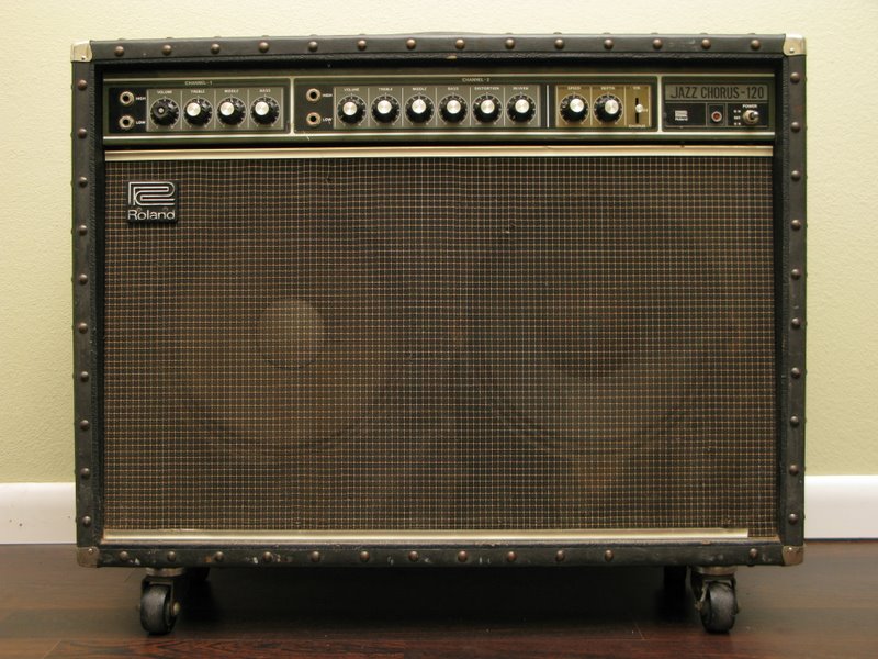
    Howdy! I recently picked up an old JC-120 at a local pawn shop. It's a little worn, but that's fine by me, I like 'em that way. One speaker has been replaced with a Pyle (which is a poor match as it is more efficient & has earlier and more aggressive break-up), the ground prong was broken off so it hummed like crazy, and the 'verb & modulation weren't working. First fix was an easy one, I scored a 'construction orange' 3-prong plug from Home Depot and the amp is now very quiet, even cranked well past noon w/ the distortion up.

    I've been keeping my eyes peeled for an early Roland speaker to match the original, but they don't seem to pop up very often (ever?) so I may go with a pair of something similar.

    The reverb and modulation seemed at first to be another easy fix as the blue wire going from the main fuses to the board was hanging loose, not able to tell if it was sloppily de soldered by some previous owner or if it just broke off. The 125mA fuse looked to be of the same make & age as the others, and I've now been using the amp for more than a week with no problems, so I don't think it was purposefully disconnected. The replacement speaker must've been wired out of phase with the other as the chorus wasn't very strong until I swapped leads on that speaker. The chorus and reverb now work quite well with one exception = the rate & depth pots have little to no affect on the chorus, which is strange as both pots measure as working and affect the vibrato in a normal, linear fashion. What would cause the pots to work correctly with vibrato & not chorus? Any suggestions for first steps in trouble-shooting this would be greatly appreciated!

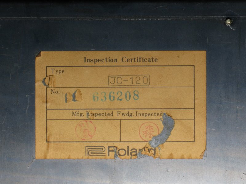
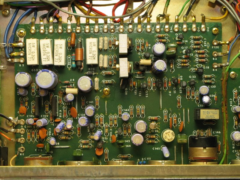
    I've got all 3 of the common schematics that float around, but I think my amp is pre-'79. The chorus board has a totally different layout than the one shown in the '79 diagram, but still uses the MN3002 unlike the later ones I've read about. I talked to Roland USA, but they don't have a service manual for anything earlier than '79.

    Last thing to note is that my reverb tank must've been replaced at some point. It's an O.C. electronics 'type 60' unit, "Manufactured by beautiful girls in Milton, Wis. under controlled atmosphere conditions". See the picture below - I got a kick out of it!






  • #2
    More pix:


    Comment


    • #3
      Well, pulled the chassis back out this morning before work and found that the underside of the board, including all the solder joints on the chorus/vibrato switch look great, clean, etc. Cleaned the switch w/ some contact cleaner, no change. Pots still work perfectly on the vibrato & not at all on the chorus. Any suggestions for what to look at next?

      FYI - I've read a few posts here about early JC-120s with the little "mystery pot" inside the rear panel. It has two wires, one purple & one green going to terminals marked 'v1' and 'v2' on the chorus board. I noted the original position and then swept it through it's range. Not sure what it does. . . any help here?

      Comment


      • #4
        CLean/schmean, did you TEST the switch contacts with an ohm meter? Are all of them functioning?
        Education is what you're left with after you have forgotten what you have learned.

        Comment


        • #5
          Thanks for popping in!

          I didn't bother probing the switch as I don't know what correct operation would look like. I guess I could try to trace the legs of each pot to the switch to see if it's something really straight forward. . .

          Comment


          • #6
            Look underneath the switch - the other side of the board, that is. There are two parallel rows of contacts. It is nothing more than a fancy version of the slide switches like Fender uses for Bright switches. If you can visualize how those work, you can visualize this. For every three legs down a row, the center one switches to the leg on one side of it or the other side. Try a couple with a meter, you'll figure the pattern out simple enough.

            Just check them all, don't bother tracing which exact ones go where. It won;t take but a couple minutes.

            Never think up reasons not to check something
            Education is what you're left with after you have forgotten what you have learned.

            Comment


            • #7
              Originally posted by Enzo View Post
              Never think up reasons not to check something
              Thanks. I'll have a chance to check it on Monday & report back.

              Comment


              • #8
                Originally posted by drasp View Post
                Thanks. I'll have a chance to check it on Monday & report back.
                Well Enzo, just as you said, probing the pins on the switch for continuity was a breeze. The switch has two rows of 8 pins for a total of 16. With the switch in the up or 'vibrato' position, there is continuity between the top pair and the pair immediately below it. In the middle or 'off' position, there is continuity between the top pair and the 3rd pair down. In the lower or 'chorus' position, there is continuity between the top pair and the 4th pair down. This same pattern is repeated with the 5th through 8th pairs. On all pairs, there appears to be essentially no resistance. I assume that this describes the function of a 'good' or working switch. Just to be sure, I re-touched the solder joints on the switch, but they already looked good under a magnifier. Where should I look next?
                Last edited by drasp; 11-17-2008, 06:16 PM.

                Comment


                • #9
                  I presume you have read this thread ?
                  http://music-electronics-forum.com/s...ead.php?t=4492
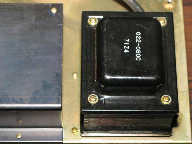
                  The smalll board connected to the power transformer wiith wire wound resistors and transistors for regulation was riddled with dry joints in one I looked at ages ago.Everything worked except the chorus which I suppose
                  shows the "chorus area" is the most sensitive area to minor power supply
                  faults.To flip the board to inspect it have to dissconnect the short wires from the transformer..thats of course if yours has one !
                  Just spotted some early cmos 4000 series in your photos..these are so cheap and prone to failure
                  possibly worth changing..snip em out clean up the debris and fit 2 x IC sockets
                  Last edited by oc disorder; 11-17-2008, 08:00 PM.

                  Comment


                  • #10
                    "The chorus and reverb now work quite well with one exception = the rate & depth pots have little to no affect on the chorus, which is strange as both pots measure as working and affect the vibrato in a normal, linear fashion. What would cause the pots to work correctly with vibrato & not chorus?"

                    Is this possible? I haven't worked on one of these for a while, but I thought that the chorus and vibrato controls were controlling the same thing in either position of the switch, the difference being whether or not there was straight signal mixed with the delayed signal or not.

                    Comment


                    • #11
                      Originally posted by oc disorder View Post
                      I presume you have read this thread ?
                      http://music-electronics-forum.com/s...ead.php?t=4492

                      Just spotted some early cmos 4000 series in your photos..these are so cheap and prone to failure
                      possibly worth changing..snip em out clean up the debris and fit 2 x IC sockets
                      I had read that thread a few times, but since the OP is complianing of weird noise instead of chorus/vibe I assumed it was a different issue entirely. Will flip the small power board tomorrow to check for problems - thanks for the tip!

                      Your suggestion about the CMOS 4000 series chips is a bit over my head, but I'll look in to it - do you have a suggestion for a correct replacement?

                      I'd still REALLY like to know what the single pot accessible by the small hole in the back of the chassis controls. One purple & one green wire going from it to 'v1' and 'v2' on the chorus PCB - shown in my pictures above. Any guesses?

                      Comment


                      • #12
                        Originally posted by oc disorder View Post
                        I presume you have read this thread ?
                        http://music-electronics-forum.com/s...ead.php?t=4492
                        The smalll board connected to the power transformer wiith wire wound resistors and transistors for regulation was riddled with dry joints in one I looked at ages ago.
                        Flipped this board yesterday & found that it'd been re-touched by someone in the past. None of the joints looked obviously bad, but I re-touched a few for good measure. No change to the chorus control issue I'm having. Anyone got any other ideas or tests I can run? This problem is really starting to frustrate me. I can find posts about this in a few places but no one that has a resolution. One person did say they'd cleaned the switch and it'd started working, but that didn't change anything in my case.

                        Another point, the replacement speaker in my amp (a Pyle) is much louder and 'edgier' than the stock speaker when the vibe/chorus is off, but the two seem much better balanced when the effect is on. Is this just a product of the way the stereo effect works or is this another symptom of my problem?

                        Comment


                        • #13
                          Another point, the replacement speaker in my amp (a Pyle) is much louder and 'edgier' than the stock speaker when the vibe/chorus is off, but the two seem much better balanced when the effect is on. Is this just a product of the way the stereo effect works or is this another symptom of my problem?
                          Although the odd speaker is not ideal its just the way it works.
                          One side is altered with respect to the other (straight signal)

                          I would try adjusting the rear control after carfully noteing where the control is.
                          In the forum Vintage Amps under the heading "Need schematic diag Roland JC120 " vintagekiki posted 3 schematics.
                          One of them is close to yours "Roland JC120&160' 79.pdf" uses the MN3002.
                          http://music-electronics-forum.com/s...56289#poststop

                          Recently I had a "Starforce USA" made in Korea by a fly by night manufacturer
                          which had a chorus and echo built in..echo worked chorus didn't.
                          There was a little trim pot which when adjusted brought the chorus into focus.
                          I'll attach a picture of the section (sorry little large 441kb) and it shows a control VR6 ? (little hard to read) connected to V1 V2 and a 4.7k resistor which your photo shows and its called (drum roll) "Chorus Adjust" !

                          So I suppose a rear mounted user accessible control in an amp from a pawn shop is a very strong contender !

                          The control may need cleaning (Caig Fader Lube or similar) and also I noticed
                          a 50k preset hanging off the MN3002 which I also highlighted which hopefully can be left untouched.

                          Could it be that simple ?

                          We wait with bated breath...
                          Attached Files

                          Comment


                          • #14
                            Unfortunately, the rear-mounted, user accessible pot doesn't have any affect on my problem. I marked it and then ran it through it's full range and while it does seem to have some affect on the chorus, it doesn't make the controls functional. Still, good to know what it does - 'focus' the chorus.

                            Comment


                            • #15
                              What would cause the pots to work correctly with vibrato & not chorus?"
                              At least in some circuit revisions the chorus mode (if I remember right) disables both of the potentiometers (speed and depth) completely and replaces them with a constant resistance value or something. That’s just a basic “feature” of those amps. I believe it’s like that in all of them. The controls are not even supposed to work in chorus mode.

                              If that remark was just off topic then here's a one final mention about something worth of checking out: In many revisions of the chorus circuit the LFO is switched on with a semiconductor switch, triggered by the output signal of the power amplifier. If the semiconductors switch (a transistor) or the trigger signal’s circuit path from the PA has failed the LFO won’t oscillate and the clock driving the BBD is locked on to a constant frequency.

                              Comment

                              Working...
                              X