Ad Widget

Collapse

Announcement

Collapse
No announcement yet.

Roland Blues Cube 30 question

Collapse
X
 
  • Filter
  • Time
  • Show
Clear All
new posts

  • #16
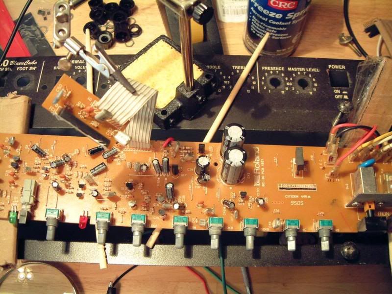
    The signal at the output transistor is full volume. when I work forward thru the connecting ribbon and on to the main board the signal was at low volume just where it connects to the main board. Continuity is good thru the ribbon. Can I remove the output board that houses the output transistor, which is mounted to the chassis, in order to take measurements? Or does it need the chassis to help dissipate heat? There are 9 small components on this gum sized board.
    Comment


    • #17
      Originally posted by Garydean View Post
      The signal at the output transistor is full volume. when I work forward thru the connecting ribbon and on to the main board the signal was at low volume just where it connects to the main board. Continuity is good thru the ribbon.
      Is it possible that the ribbon cable opens up under stress at either end? Try flexing the ends while checking continuity. Try bypassing the ribbon cable one trace a a time with a wire jumper.

      Originally posted by Garydean View Post
      Can I remove the output board that houses the output transistor, which is mounted to the chassis, in order to take measurements? Or does it need the chassis to help dissipate heat? There are 9 small components on this gum sized board.
      I don't know, if you turn on the amp with the chip unheatsinked does it start to get hot? They often do, leading to overheating and burn out. To be safe either leave it on the chassis or screw it down to a piece of aluminum sheet as a temporary heatsink.

      Comment


      • #18
        thanks again Bill,
        I put the output board back on the chassis and turned on the amp. Works fine.... jiggled the ribbon and got an intermittent signal. You were right the ribbon or solder points need t be looked at. I guess my best bet is to rework both sides just in case.

        Comment


        • #19
          GAry - coupling caps are there to connect to stages of a circuit together. The caop blocks any DC difference but passes signal through. SO to test one for signal, if the signal is on one end, it should show up on hte other end too. The DC on one side should stay where it is though.
          Education is what you're left with after you have forgotten what you have learned.

          Comment


          • #20
            So I'm only gonna see those low value, orange drop, lemon drop, dog doo drop and gum drop caps in the signal path blocking DC? Higher value polar caps will be seen in the supply line filtering and leveling DC? Generally speaking? How about ceramic, are they just tone shapers, different values block certain frequencies, but I see them in supply lines as well? and tantalum? Any general rule to follow, besides "there are no rules"?

            thank you.

            Comment


            • #21
              Originally posted by Garydean View Post
              So I'm only gonna see those low value, orange drop, lemon drop, dog doo drop and gum drop caps in the signal path blocking DC? Higher value polar caps will be seen in the supply line filtering and leveling DC? Generally speaking?
              Generally speaking yes, but the values of the caps relate to the impedance of the circuit. In tube amps coupling caps will rarely get above .22uF, while in a solid state amp they can easliy be in the 10uF range.

              Originally posted by Garydean View Post
              How about ceramic, are they just tone shapers, different values block certain frequencies, but I see them in supply lines as well?
              Small value caps used on supply lines are "decoupling" caps. They basically serve the same purpose as the larger filters but work in frequency ranges that aren't efficently covered by the larger caps.

              Originally posted by Garydean View Post
              ...and tantalum? Any general rule to follow, besides "there are no rules"?
              Caps are caps, some types work better at certain applications, but they all serve the same basic function. Sometimes a designer will chose the type of cap based upon size, or cost, or temperature range, or sometimes on their audio qualities (most of which have been debated here already).

              Comment


              • #22
                good answers Bill.... I appreciate your knowledge.

                Comment

                Working...
                X